background image

Operation - 1370, 1385, 1395, 13114  Backsaver Auger

29

PTO Driveline Length Check

Due to variations in distances between tractor PTO 
shafts and implement input shafts, drivelines may 
need to be shortened or a longer shaft may be 
required. 

When fitting the implement to the tractor, the 
PTO driveline, with telescoping sections, must 
be inspected. When the sections are at the most 
compressed operating position, the sections must 
not “bottom out”. 

At its shortest length, there must be at least 2 in. 
(50.8 mm) of clearance between each section end 
and opposite section end at the most compressed 
operating position. 

When the sections are at the most extended 
position, there must be sufficient engagement 
between the sections. 

At its farthest operating extension, a minimum 
section engagement of 33% of shaft length must 
be maintained.

WARNING

AVOID INJURY OR DEATH

• 

Do NOT exceed the rated implement PTO speed.

• 

Stay clear of rotating driveline.

• 

Keep bystanders away.

• 

Keep hands, feet, clothing and long hair away.

• 

Keep PTO shields and all guards in place.

• 

Disengage PTO, move the tractor controls to the 
Neutral position, stop the engine and make sure all 
rotating components are stopped before leaving the 
operator’s position.

• 

Do NOT service the tractor or implement with the 
PTO engaged.

• 

Do NOT service the implement in a raised position 
unless properly blocked and with all rotating 
components stopped.

• 

Disengage PTO for road travel.

PTO Driveline Bottoming Out Check

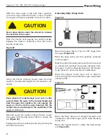
Stop the engine and leave the operator’s position. 
See See 

“Entering & Leaving The Operator’s 

Position” on page 26

Make sure the PTO driveline and all rotating 
components have come to a complete stop before 
leaving the operator’s position (if applicable).

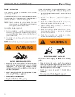
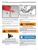
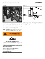
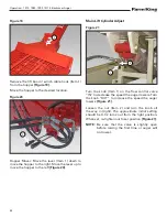
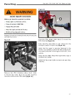
Figure 12

1.  Disconnect the PTO driveline from the tractor and 

slide the PTO driveline together until fully retracted 
(compressed).

2.  Measure the retracted (compressed) length of PTO 

driveline 

[Figure 12]

.

3.  Extend the PTO driveline 2 in. (50.8 mm) from the 

retracted length and place a mark on the inner guard 
at the end of the outer guard 

[Figure 12].

4.  Reattach the PTO driveline to the tractor PTO shaft.

5.  Enter the operator’s position. Start the engine.

6.  With the rear PTO DISENGAGED, raise and lower 

the implement and watch the PTO driveline extend 
and retract.

7.  If the outer PTO driveline guard slides in (retracts) 

over the mark at any point of travel, the PTO driveline 
needs to be shortened.

MARK INNER 

GUARD HERE

RETRACTED

(COMPRESSED LENGTH)

2” (50.8 mm)

Summary of Contents for 1370

Page 1: ...062022 FK428 OPERATOR AND PARTS MANUAL BACKSAVER AUGER Models 1370 1385 1395 13114...

Page 2: ......

Page 3: ...IFICATIONS 129 WARRANTY 139 Manufacturer s Statement For technical reasons Farm King reserves the right to modify machinery design and specifications provided herein without any preliminary notice Inf...

Page 4: ...1370 1385 1395 13114 Backsaver Auger 2...

Page 5: ...me and I have been thoroughly instructed as to care adjustments safe operation and applicable warranty policy Date Customer Owner Signature Remove this Warranty Registration Form from the Operator An...

Page 6: ...Warranty Registration Form 1370 1385 1395 13114 Backsaver Auger 4...

Page 7: ...and part identification of the Farm King equipment READ AND UNDERSTAND THIS OPERATOR AND PARTS MANUAL BEFORE OPERATING YOUR FARM KING EQUIPMENT If you have any questions see your Farm King dealer Thi...

Page 8: ...Introduction 1370 1385 1395 13114 Backsaver Auger 6...

Page 9: ...anty or guarantee of any kind written or expressed implied or otherwise with regard to the information contained within this manual Farm King assumes no responsibility for any errors that may appear i...

Page 10: ...ction 1370 1385 1395 13114 Backsaver Auger 8 EQUIPMENT IDENTIFICATION PTO DRIVELINE INPUT BOX ELBOW BOOM BRIDGING DISCHARGE SPOUT HYDRAULIC CYLINDER UNDERCARRIAGE WHEEL HOPPER INTAKE AUGER JACK SAFETY...

Page 11: ...y Rules For PowerTake Off PTO Driven Equipment 12 Machine Requirements And Capabilities 13 Transport Safety 13 FIRE PREVENTION 14 Maintenance 14 Operation 14 Fire Extinguishers 14 Electrical 14 Hydrau...

Page 12: ...Safety 1370 1385 1395 13114 Backsaver Auger 10...

Page 13: ...or who is taking prescription drugs must get medical advice to determine if he or she can safely operate a machine and the equipment Understand the written instructions rules and regulations The writt...

Page 14: ...in an area clear of bystanders especially small children DO NOT permit personnel to be in the work area when operating the equipment The equipment must be used ONLY on approved tractors transport veh...

Page 15: ...Install blocks underneath and support the equipment securely before working under raised equipment Keep bystanders clear of moving parts and the work area Keep children away Use increased caution on s...

Page 16: ...late Electrical Check all electrical wiring and connections for damage Keep the battery terminals clean and tight Repair or replace any damaged part or wires that are loose or frayed Battery gas can e...

Page 17: ...ryone clear when operating the hopper mover DANGER ELECTROCUTION HAZARD Keep away from power lines electrocution can occur without direct contact CAUTION Owners and operators should allow only authori...

Page 18: ...low the instructions on all the signs decals that are on the equipment Replace any damaged signs decals and be sure they are in the correct locations Equipment signs are available from your Farm King...

Page 19: ...ecal Identification Figure 4 Electrocution Hazard PN 909745 Item 1 Upending Hazard PN 960569 Item 2 Driveline Hazard PN 904585 Item 3 PTO Warning PN 108431 Item 4 PTO Important PN 960371 Item 5 Check...

Page 20: ...1395 13114 Backsaver Auger 18 Caution PN 963206 Item 8 Danger PN 961016 Item 9 Run Auger PN 961015 Item 10 Intake Caution PN 917765 Item 11 List Caution PN 961017 Item 12 Figure 5 PTO rpm PN 936775 I...

Page 21: ...19 Model Number Decals 1370 PN 910575 1385 PN 910577 1395 PN 910578 13114 PN 928081 BS13 Farm King 4 5 x 30 5 PN 910601 BS13114 Farm King 7 1 x 44 9 PN 935029 Reflectors Other Decals Amber PN 52773 00...

Page 22: ...ineers ASABE and the Occupational Safety and Health Administration OSHA Anyone who will be operating and or maintaining the auger must read and clearly understand ALL Safety Operating and Maintenance...

Page 23: ...avingThe Operator s Position 26 CONNECTINGTOTRACTOR 26 HitchingThe Equipment 26 ConnectingThe PTO Driveline 27 PTO Driveline Length Check 29 PTO Driveline Bottoming Out Check 29 ReducingThe PTO Drivel...

Page 24: ...Operation 1370 1385 1395 13114 Backsaver Auger 22...

Page 25: ...used 1 Lubricate the equipment per the schedule outline in the Maintenance Section 2 Check the augers Remove any material build up or debris that has become entangled 3 Make sure that all guards and s...

Page 26: ...equipment Always keep PTO shields and all guards in place when using PTO driven equipment Disengage PTO for road travel Keep hands feet and clothing away Check the following mechanical items after 1 h...

Page 27: ...ith a 6 spline 1 3 8 standard or 21 spline 1 3 8 optional when used with the 13 Backsaver Auger Minimum HP 540 RPM PTO Auger Model Minimum Tractor HP 1370 80 HP 1385 90 HP 1395 100 HP 13114 165 HP Dra...

Page 28: ...ractor backwards aligning the drawbar with the Backsaver Auger hitch NOTE The jack may need to be lowered or raised for proper alignment of the drawbar and hitch If the Backsaver Auger hitch needs to...

Page 29: ...a retaining pin with a locking device Figure 9 Install the hitch pin Item 1 and retaining pin to securely fasten the Backsaver Auger hitch to the tractor drawbar Figure 9 Attach the safety chain Item...

Page 30: ...y chain Item 2 Figure 10 NOTE The PTO driveline must have a means to retain it to the PTO shaft on the tractor WARNING AVOID INJURY OR DEATH Do NOT exceed 540 RPM PTO if equipped with chain drive Do N...

Page 31: ...ke sure all rotating components are stopped before leaving the operator s position Do NOT service the tractor or implement with the PTO engaged Do NOT service the implement in a raised position unless...

Page 32: ...position if equipped Enter the operator s position See Entering The Operator s Position in the Operation section Start the engine Raise or lower the three point implement to get the shortest distance...

Page 33: ...iveline length by 1 667 to determine the PTO driveline Maximum Operating Length i e 25 5 in 647 7 mm x 1 667 42 5 in 1079 7 mm Maximum Operating Length 4 Attach the PTO driveline to the tractor PTO ou...

Page 34: ...an quickly damage the system NOTE Make sure the quick couplers are fully engaged If the quick couplers do not fully engage check to see that the couplers are the same size and type To Connect Figure 1...

Page 35: ...perating the winch Never guide the cable with your hands Never let wire rope slip through your hands Frayed kinked or damaged wire rope must be replaced immediately Always stand clear and keep others...

Page 36: ...Figure 20 Main Lift Cylinder Adjust Figure 21 Turn the knob Item 1 on the flow control valve IN to decrease the speed the auger lowers Turn the knob OUT to increase the speed the auger lowers Figure 2...

Page 37: ...provide adequate anchoring of the intake end to prevent sudden tipping Disconnect power of electrical driven units before resetting motor overloads To avoid tipping make sure auger is empty before at...

Page 38: ...weight may cause damage to the underside of the auger or to the bin Back the auger into position above the bin Lower the auger until the downspout Item 1 enters the bin Figure 22 Engage the tractor s...

Page 39: ...r augers and intake auger can move grain to the main auger without overflowing the hopper When the rear compartment is empty close the gate disengage the PTO and lower engine RPM speed Figure 26 Move...

Page 40: ...g brake if equipped WARNING AVOID INJURY OR DEATH Do NOT exceed 540 RPM PTO if equipped with chain drive Do NOT exceed 1000 RPM PTO if equipped with optional M1000 gearbox Keep PTO shields and all gua...

Page 41: ...32 kph Do not move or transport the auger unless the hopper and intake auger are in the raised transport position and securely fastened before transporting Comply with federal state local and provinc...

Page 42: ...be supported by the transport chain whenever the auger is moved If the weight of the intake auger is on the winch the winch may be damaged during transport Lower the hopper until the transport chain...

Page 43: ...ine safety chain Item 1 Retract the collar Item 2 and slide the PTO driveline off the tractor PTO shaft Figure 31 Figure 32 Place the PTO holder chain Item 1 around the PTO driveline Figure 32 Fully r...

Page 44: ...Operation 1370 1385 1395 13114 Backsaver Auger 42...

Page 45: ...Service 54 SAFETY SIGN DECAL INSTALLATION 54 ELECTRIC HOPPER CONTROL BOXTROUBLESHOOTING 55 Hopper Will Not Move Left Or Right 55 Hopper Will Only Move In One Direction 55 Remote Control Functions Corr...

Page 46: ...Maintenance 1370 1385 1395 13114 Backsaver Auger 44...

Page 47: ...Discharge gate s not open enough Open the gate s to allow a faster grain flow to the hopper intake auger Tractor RPM set to low Raise tractor RPM to proper setting Lights do not function Loose connect...

Page 48: ...r service Untrained operators and failure to follow instructions can cause injury or death DESCRIPTION SERVICE PROCEDURES Check Clean Lube Change Adjust Drain Daily Maintenance or every 8 hours 1 CV J...

Page 49: ...nner Some regulations require that certain spills and leaks on the ground must be cleaned in a specific manner See local state and federal regulations for the correct disposal Locations Lubricate the...

Page 50: ...n the hopper auger drive shaft Figure 36 Figure 37 Apply two pumps of grease to the intake drive shaft side Item 1 Figure 37 Figure 38 Apply two pumps of grease to the intake hopper drive shaft Item 1...

Page 51: ...igure 42 Figure 43 Apply two pumps of grease to the RH lower lift arm pivot Item 1 Repeat procedure on the LH lower lift arm pivot Figure 43 Figure 40 Apply three pumps of grease to the rod end of the...

Page 52: ...le Changing Gear Oil Remove the fill drain plug Item 1 and siphon all the gear oil from the gearbox Figure 45 Fill with SAE 75W 90 synthetic gear oil to the bottom of the plug hole Install fill drain...

Page 53: ...lace chock blocks behind and in front the auger tire Place a jack under the axle frame on the side the wheel is to be replaced Raise the jack until the wheel is slightly off the ground NOTE Place bloc...

Page 54: ...e cables should be kept well lubricated Cleaning Periodic cleaning of cables by using a stiff brush and kerosene or with compressed air or live steam and re lubricating will help to lengthen cable lif...

Page 55: ...t NOTE If the nut is fully tightened and bottoms out against the eye of the adjustment bolt the cable will need to be loosened and additional adjustments will be made on the opposite end of the cable...

Page 56: ...with planks if required ReturnTo Service After the equipment has been in storage it is necessary to follow a list of items to return the equipment to service Be sure all shields and guards are in plac...

Page 57: ...m meter to check the voltage at the drive wheel output wires There should be system voltage when pressing the left right button on the control box If there is voltage in both directions the motor may...

Page 58: ...ould be system voltage when pressing the lift lower button on the control box If there is voltage in both directions the motor may be at fault and will need to be replaced If there is voltage in only...

Page 59: ...turn off and the green LED will turn on A fully discharged unit will take up to 3 hours to recharge Use only approved chargers Indicator Lights The receiver has two LED indicators the red ERROR CODE...

Page 60: ...Maintenance 1370 1385 1395 13114 Backsaver Auger 58 PART IDENTIFICATION CONTROL BOX SZ000997 Figure 53 11 1 9 1 4 4 3 5 2 10 7 7 6...

Page 61: ...Maintenance 1370 1385 1395 13114 Backsaver Auger 59 8 6 7 7 11 2 3 9 1 1 Figure 54...

Page 62: ...ESCRIPTION QTY 1 931903 WIRE HARNESS 1 2 931904 30 AMP BREAKER 1 3 931905 70 AMP BREAKER 1 4 931906 60 AMP RELAY 2 5 931907 12V 160 AMP CONTACTOR 1 6 931908 2 POSITION SWITCH 1 7 931909 3 POSITION SWI...

Page 63: ...ELS 72 LIFT ARMS 70 MODELS 74 LIFT ARMS 85 95 MODELS 76 LIFT ARMS 114 MODELS 78 TUBES 70 MODELS 80 TUBES 85 MODELS 82 TUBES 95 MODELS 84 TUBES 114 MODELS 88 TUBE COMPONENTS 70 MODELS 90 FirstTube Inta...

Page 64: ...MODELS 100 INPUT BOX 70 85 95 MODELS 102 INPUT BOX 114 MODELS 106 IDLER 110 M1000 GEARBOX INPUT BOX 70 85 95 MODELS 112 M1000 GEARBOX INPUT BOX 114 MODELS 116 INTAKE AUGER 120 SINGLE FLIGHTING HOPPER...

Page 65: ...Parts Identification 1370 1385 1395 13114 Backsaver Auger 63...

Page 66: ...ON The parts identification section list descriptions part numbers and quantities for all North America Base Model BS13 Series Augers Contact your Farm King dealer for additional parts information UND...

Page 67: ...1 2 SAE FLAT WASHER PL 8 7 84270 5 8 X 1 3 4 HEX BOLT PL 2 8 84299 5 8 X 2 HEX BOLT GR 5 PL 8 9 86273 7 16 LOCK NUT PL 4 10 87553 1 2 X 1 75 HEX BOLT UNC GR5 PL 8 11 906572 ASSY STUB AXLE 13 X70 2 12...

Page 68: ...Parts Identification 1370 1385 1395 13114 Backsaver Auger 66 UNDERCARRIAGE 85 95 MODELS DETAIL A A 6 2 8 1 9 16 15 14 13 10 11 5 2 7 3 4 12 919020...

Page 69: ...84270 5 8 X 1 3 4 HEX BOLT PL 2 6 84299 5 8 X 2 HEX BOLT GR 5 PL 8 7 86273 7 16 LOCK NUT PL 4 8 87553 1 2 X 1 75 HEX BOLT UNC GR5 PL 8 9 906573 STUB AXLE ASSEMBLY 2 10 919464 TUBE UNDERCARRIAGE ARM B...

Page 70: ...Parts Identification 1370 1385 1395 13114 Backsaver Auger 68 UNDERCARRIAGE 114 MODELS 1 3 9 12 6 5 2 5 13 16 14 10 8 4 15 17 5 7 11 927749...

Page 71: ...UT PL 9 6 81672 5 8 X 4 1 2 HEX BOLT PL 4 7 84268 5 8 X 1 1 2 HEX BOLT PL 4 8 84346 3 4 X 2 1 2 HEX BOLT PL 16 9 905736 UNDERCARR PIN SLEEVE 3 1 6 ID X 3 1 2 OD X 1 1 2 2 10 909191 ASSY STUB SHAFT AND...

Page 72: ...XLE 70 MODELS ITEM PART NUMBER DESCRIPTION QTY 1 810010 NUT SLOTTED 7 8 UNF BR 1 2 904902 GREASE GRADE 2 28g 3 906466 STUB AXLE WELDMENT 1 4 967713 7 8 SAE FLAT WASHER BR 1 5 967731 HUB CTD H611 COMPL...

Page 73: ...85 95 MODELS ITEM PART NUMBER DESCRIPTION QTY 1 81207 3 16 X 2 COTTER PIN BR 1 2 904902 GREASE GRADE 2 32g 3 906467 STUB AXLE WELDMENT 1 4 960586 HUB CTD H618 COMPLETE ASSY 1 5 967218 1 SAE FLAT WASH...

Page 74: ...Parts Identification 1370 1385 1395 13114 Backsaver Auger 72 STUB AXLE 114 MODELS 2 4 3 6 4 5 4 909191...

Page 75: ...73 ITEM PART NUMBER DESCRIPTION QTY 1 904902 GREASE GRADE 2 28 g 2 909190 STUB AXLE WELDMENT 1 3 92812442 ARROW RIM WASHER 1 1 4 x 10 GA BR 1 4 909190 HUB CTD H817 COMPLETE ASSEMBLY 1 5 967252 3 16 x...

Page 76: ...Identification 1370 1385 1395 13114 Backsaver Auger 74 LIFT ARMS 70 MODELS HYDRAULIC LAYOUT 7 29 23 15 19 24 16 18 2 27 8 9 6 4 1 3 5 14 18 2 13 18 2 22 22 22 22 10 11 20 25 21 17 2 18 12 18 2 26 28 9...

Page 77: ...500 DIA 1 13 960629 LIFT ARM CLEV PIN WELDT 1 500 DIA 2 14 960630 TOPYOKE PIN WELDT 1 500 DIA 1 15 960631 LIFT ARM CLEVIS PIN WELDT 1 000 DIA 2 16 960632 LIFT ARM PIVOT PIN WELDT 1 500 DIA 1 17 96069...

Page 78: ...ification 1370 1385 1395 13114 Backsaver Auger 76 LIFT ARMS 85 95 MODELS HYDRAULIC ROUTING 8 25 22 21 21 11 17 2 26 27 16 18 23 9 6 4 1 5 3 14 19 20 7 12 13 19 20 24 19 20 21 15 17 2 14 19 20 21 21 28...

Page 79: ...0 DIA 1 12 960688 13 LINK WELDMENT 1 13 960690 BOTTOM CYL PIN WELDT 2 000 DIA 1 14 960692 TOP CYLINDER PIN WELDT 2 000 DIA 3 15 960694 WELDMENT TOPYOKE PIN 1 500 DIA 1 16 960695 LIFT ARM CLEVIS PIN 1...

Page 80: ...ntification 1370 1385 1395 13114 Backsaver Auger 78 LIFT ARMS 114 MODELS A 1 7 4 20 DETAIL A 27 28 17 27 28 18 12 13 27 28 15 29 29 6 4 14 21 29 33 34 32 31 11 8 5 10 29 3 30 16 27 28 22 2 19 23 9 24...

Page 81: ...750 DIA 1 15 908476 LIFT ARM PIN WELDT 2 000 DIA 2 16 908478 CYL PIN ROD 2 000 DIA 1 17 908480 UPPER LIFT ARM PIN 2 000 DIA 1 18 908490 LIFT PIN ROD 2 000 DIA 1 19 913193 P CLIP 0 75 4 20 914760 LIFT...

Page 82: ...er 80 TUBES 70 MODELS DETAIL A DETAIL B DETAIL C DETAIL D DETAIL E SECTION F F A B C D E F F 40 3 5 28 18 19 31 32 8 16 15 7 35 34 24 2 6 38 25 22 23 27 26 16 8 35 34 15 11 7 33 15 11 7 37 7 30 39 9 6...

Page 83: ...ID X 3 1 2 OD X 1 1 2 2 18 907442 UPPER CABLE BUNDLE 1 19 907443 LOWER CABLE BUNDLE 1 20 910025 1 2 X 4 GR8 HEX BOLT PL 6 21 918739 SHAFT FLTG SQUARE 3 22 960057 08 FNPT 2 WAY BALL VALVE 1 23 960152...

Page 84: ...5 MODELS DETAIL A DETAIL B DETAIL C DETAIL D DETAIL E SECTION F F A B C D E F F 43 27 3 5 25 2 6 31 8 16 38 37 33 19 18 15 7 21 41 26 23 4 24 35 40 7 36 34 29 8 16 38 37 30 15 7 9 6 10 28 39 38 8 16 2...

Page 85: ...E BUNDLE 1 19 907445 UPPER CABLE BUNDLE 1 20 910025 1 2 X 4 GR8 HEX BOLT PL 6 21 918739 SHAFT FLTG SQUARE 3 22 960057 08 FNPT 2 WAY BALL VALVE 1 23 960152 ADAPTOR STRAIGHT 10 MJIC X 8 MNPT 1 24 960162...

Page 86: ...S DETAIL A DETAIL B DETAIL C DETAIL D DETAIL E DETAIL F DETAIL G A B C D E F G 3 5 35 48 45 7 21 22 8 17 37 43 41 40 8 17 42 25 7 16 17 8 39 38 7 16 17 8 47 44 24 23 27 26 7 15 8 13 13 17 28 6 29 18 1...

Page 87: ...PIN SLEEVE 3 1 6 ID X 3 1 2 OD X 1 1 2 2 19 907444 LOWER CABLE BUNDLE 1 20 907445 UPPER CABLE BUNDLE 1 21 909942 MAIN BRIDGINGYOKE PLATE 2 22 909943 MAIN BRIDGINGTIE PLATE 1 23 909944 UPPER BRIDGINGYO...

Page 88: ...tinued DETAIL A DETAIL B DETAIL C DETAIL D DETAIL E DETAIL F DETAIL G A B C D E F G 3 5 35 48 45 7 21 22 8 17 37 43 41 40 8 17 42 25 7 16 17 8 39 38 7 16 17 8 47 44 24 23 27 26 7 15 8 13 13 17 28 6 29...

Page 89: ...BER DESCRIPTION QTY 42 964001 1 X 7 16 X 10GA FLAT WASHER PL 16 43 964565 1 2 CABLE CLAMP PL 16 44 964587 1 2 CABLETHIMBLE 4 45 967284 BOLT FLAT HEAD SOCKET 5 8 X 1 3 4 PL 4 46 967463 HOSE 8 X 8MNPT X...

Page 90: ...1395 13114 Backsaver Auger 88 TUBES 114 MODELS DETAIL A DETAIL B SECTION C C DETAIL D SECTION E E SECTION F F DETAIL G D G B A E E F F C C 26 2 25 28 16 3 18 7 9 3 27 1 24 17 22 20 21 23 6 10 10 14 1...

Page 91: ...048 1 2 SAE FLAT WASHER PL 24 12 84277 1 2 X 1 1 2 HEX BOLT PL 12 13 84299 5 8 X 2 HEX BOLT GR 5 PL 8 14 86273 7 16 LOCK NUT PL 36 15 905807 UPPER LIFT ARM PIN COLLAR 2 16 910025 1 2 X 4 GR8 HEX BOLT...

Page 92: ...0 10 1 3 86170 3 8 X 1 HEX BOLT GR 5 PL 7 4 918974 WELDT BS1370 BOTTOMTUBE 1 5 928650 WELDT BS13114 BOTTOM FLTG 1 6 960144 5 8 X 11 HYD LINE JIC FEMALE ENDS 1 7 960468 5 8 X 13 4 HYD LINE JIC FEMALE E...

Page 93: ...FLTG ADJ 1 7 918817 WELDT TOP PLATE 1 8 918828 WELDT TOP FLANGE CAP 1 9 918969 WELDT BS1370TOPTUBE 1 10 920211 GASKET FLTGTENSIONER 1 11 929845 WELDT BS1370TOP FLTG 1 12 960035 END BEARING SLEEVE 1 13...

Page 94: ...BS1385 BOTTOMTUBE 1 5 928650 WELDT BS13114 BOTTOM FLTG 1 6 960200 HYD LINE 5 8 OD X 9 7 1 7 960467 HYD LINE 5 8 X 15 10 1 8 960639L HYDRAULIC LINE CLAMP 6 SecondTube ITEM PART NUMBER DESCRIPTION QTY 1...

Page 95: ...918816L PLATE TOP FLTG ADJ 1 7 918817 WELDT TOP PLATE 1 8 918828 WELDT TOP FLANGE CAP 1 9 920211 GASKET FLTGTENSIONER 1 10 928652 WELDT BS13114TOP FLTG 1 11 960035 END BEARING SLEEVE 1 12 960037 SLOTT...

Page 96: ...BS1385 BOTTOMTUBE 1 5 928650 WELDT BS13114 BOTTOM FLTG 1 6 960200 HYD LINE 5 8 OD X 9 7 1 7 960467 HYD LINE 5 8 X 15 10 1 8 960639L HYDRAULIC LINE CLAMP 6 SecondTube ITEM PART NUMBER DESCRIPTION QTY 1...

Page 97: ...ts Identification 1370 1385 1395 13114 Backsaver Auger 95 ThirdTube ITEM PART NUMBER DESCRIPTION QTY 1 918836 WELDT BS13 10 EXTENSION 95 MODELS 1 2 929701 WELDT BS13 EXTENSION FLTG 95 MODELS 1 1 2 F19...

Page 98: ...918816L PLATE TOP FLTG ADJ 1 7 918817 WELDT TOP PLATE 1 8 918828 WELDT TOP FLANGE CAP 1 9 920211 GASKET FLTGTENSIONER 1 10 928652 WELDT BS13114TOP FLTG 1 11 960035 END BEARING SLEEVE 1 12 960037 SLOTT...

Page 99: ...UMBER DESCRIPTION QTY 1 812711 JIC UNION 10 10 2 2 81530 1 4 X 1 3 4 HEX BOLT GR5 PL 1 3 81925 HEX BOLT 5 16 X 1 3 4 PL 7 4 931881 CLAMP TWIN 8 5 928650 WELDT BS13114 BOTTOM FLTG 1 6 933101 WELDT BS13...

Page 100: ...Y 1 81925 HEX BOLT 5 16 X 1 3 4 PL 4 2 927876 HYDRAULIC LINE 5 8 2 3 931881 CLAMP TWIN 4 4 926892 WELDT BS13114 CENTERTUBE 1 5 928651 WELDT BS13114 CENTER FLTG 1 ThirdTube ITEM PART NUMBER DESCRIPTION...

Page 101: ...918817 WELDT TOP PLATE 1 7 918828 WELDT TOP FLANGE CAP 1 8 920211 GASKET FLTGTENSIONER 1 9 926896 WELDT BS13114TOPTUBE 1 10 928652 WELDT BS13114TOP FLTG 1 11 960035 END BEARING SLEEVE 1 12 960037 SLOT...

Page 102: ...entification 1370 1385 1395 13114 Backsaver Auger 100 BRIDGING 114 MODELS DETAIL A DETAIL B DETAIL C A 11 5 3 10 29 2 9 27 28 26 29 2 23 20 19 18 17 7 8 24 25 16 3 4 15 6 1 3 12 14 13 30 21 22 4 3 B C...

Page 103: ...ER 16 12 928093 WELDT TRUSS BEAM 4 13 928096 WELDT TRUSS BEAM 2 14 928101 WELDT TRUSS BEAM 6 15 928103 PLATE CROSS BRACE 6 16 928118L PLATE CROSS BRACE 2 17 928121 BRKT TRUSS SUPPORT 1 18 928122 BRKT...

Page 104: ...Parts Identification 1370 1385 1395 13114 Backsaver Auger 102 INPUT BOX 70 85 95 MODELS 10 2 6 14 1 17 15 9 3 9 7 3 18 12 16 13 4 8 11 5 19 1 7 3 930571 930611...

Page 105: ...1 3 8 X 6 CV 1385 1395 MODELS 1 6 81549 5 16 X 3 4 HEX BOLT PL 2 7 84039 WASHER 3 8 SAE FLAT PL 7 8 84346 3 4 X 2 1 2 HEX BOLT PL 1 9 86170 3 8 X 1 HEX BOLT GR 5 PL 5 10 909277 MANUAL HOLDER 3 1 2 X...

Page 106: ...RIPTION QTY 1 811790 3 4 X 4 1 2 HEX BOLT GR5 PL 1 2 812362 5 16 LOCK NUT PL 4 3 812363 3 8 LOCK NUT PL 2 4 812364 1 2 LOCK NUT PL 10 14 17 19 21 22 1 5 30 22 22 20 22 31 22 2 45 7 24 15 4 34 22 32 18...

Page 107: ...P ACCESS 1 22 917483 BOLT FL 0 313NC X 1 00 GR5 PL 22 23 918913 TUBE M1000 SHAFT SPACER 1 24 919354 ASSY COUPLING H5018 1 25 919368 BEARING FLANGE 2 BOLT PL 4 26 919377 BRKT BEARING MOUNT 1 27 919378...

Page 108: ...Parts Identification 1370 1385 1395 13114 Backsaver Auger 106 INPUT BOX 114 MODELS 9 7 4 15 8 10 2 5 11 14 1 6 3 12 1 13 930619...

Page 109: ...F2306 PTO 1 3 8 X 6 U JOINT 1 3 8 X 6 CV 1 5 81549 5 16 X 3 4 HEX BOLT PL 2 6 84039 WASHER 3 8 SAE FLAT PL 1 7 904580 SAFETY CHAIN PLATE 1 8 906284 HOOK SAFETY CHAIN ASSEMBLY 1 9 909195 JACK 1 10 9092...

Page 110: ...nued ITEM PART NUMBER DESCRIPTION QTY 1 812362 5 16 LOCK NUT PL 4 2 812363 3 8 LOCK NUT PL 2 3 812364 1 2 LOCK NUT PL 10 8 21 22 22 1 33 22 20 30 35 24 15 3 22 5 6 31 22 1 19 17 14 34 4 11 16 38 43 25...

Page 111: ...46 COVER GEARBOX ACCESS 1 21 917447 COVER TOP ACCESS 1 22 917483 BOLT FL 0 313NC X 1 00 GR5 PL 18 23 918913 TUBE M1000 SHAFT SPACER 1 24 919354 ASSY COUPLING H5018 1 25 919368 BEARING FLANGE 2 BOLT PL...

Page 112: ...Parts Identification 1370 1385 1395 13114 Backsaver Auger 110 IDLER SECTION A A A A 4 8 1 3 7 5 9 6 2 919378...

Page 113: ...8 LOCK NUT PL 4 2 919363 SHAFT REVERSE PTO 1 3 919368 BEARING FLANGE 2 BOLT PL 4 4 919379 WELDT IDLER 1 5 919438 H80B9 SPROCKET 1 375 BORE 1 6 960180 U JOINT SPROCKET KEY 313 SQ X 1 375 1 7 965917 1 3...

Page 114: ...Parts Identification 1370 1385 1395 13114 Backsaver Auger 112 M1000 GEARBOX INPUT BOX 70 85 95 MODELS 18 12 16 3 7 7 9 9 3 14 1 17 17 15 13 5 11 4 8 19 7 1 3 10 2 6 20 932952...

Page 115: ...4 HEX BOLT PL 2 7 84039 WASHER 3 8 SAE FLAT PL 7 8 84346 3 4 X 2 1 2 HEX BOLT PL 1 9 86170 3 8 X 1 HEX BOLT GR 5 PL 5 10 909277 MANUAL HOLDER 3 1 2 X 12 1 11 910287 HOOK SAFETY CHAIN ASSEMBLY 1 12 91...

Page 116: ...ion 1370 1385 1395 13114 Backsaver Auger 114 M1000 Gearbox Input Box 70 85 95 Models Continued DETAIL A 4 2 2 7 9 15 30 12 14 23 24 17 26 18 4 2 27 4 11 25 11 4 29 2 32 33 2 21 16 19 22 3 10 20 5 1 28...

Page 117: ...910947 M1000 SPLINE STUB SHAFT 1 14 911001 HELICAL GEARBOX PLATE 1 15 911083 M1000 HGBOX GUARD 1 16 911111 PTO HOLDER ARM WELDT 1 17 911130 KEY 3 8 SQ X 100MM 1 18 911163 KEY 5 16 SQ X 140MM 1 19 9119...

Page 118: ...Parts Identification 1370 1385 1395 13114 Backsaver Auger 116 M1000 GEARBOX INPUT BOX 114 MODELS 11 1 13 12 9 4 14 6 1 3 2 10 5 7 15 8 16 932953...

Page 119: ...X 21 U JOINT 1 3 8 X 21 CV 1 5 81549 5 16 X 3 4 HEX BOLT PL 2 6 84039 WASHER 3 8 SAE FLAT PL 1 7 904580 SAFETY CHAIN PLATE 1 8 906284 HOOK SAFETY CHAIN ASSEMBLY 1 9 909195 JACK 1 10 909277 MANUAL HOL...

Page 120: ...fication 1370 1385 1395 13114 Backsaver Auger 118 M1000 Gearbox Input Box 114 Models Continued 28 31 32 24 11 3 3 21 22 11 26 19 25 16 18 22 2 10 1 7 9 3 1 12 8 14 23 17 29 30 4 20 22 5 13 1 3 15 27 6...

Page 121: ...EARBOX M1000 HELICAL 1 13 910947 M1000 SPLINE STUB SHAFT 1 14 911001 HELICAL GEARBOX PLATE 1 15 911083 M1000 HGBOX GUARD 1 16 911111 PTO HOLDER ARM WELDT 1 17 911130 KEY 3 8 SQ X 100mm 1 18 911163 KEY...

Page 122: ...dentification 1370 1385 1395 13114 Backsaver Auger 120 INTAKE AUGER 18 12 10 16 17 1 9 2 6 2 10 2 13 11 3 8 4 2 7 14 15 28 2 32 0 19 5 28 40 41 31 33 30 22 38 37 36 29 34 35 39 26 23 21 22 27 24 25 25...

Page 123: ...WELDT INTAKE FLTG HOLDER 1 18 918978 WELDT HANGER BRKT 1 19 931901 LATCH SLOTTED 2 20 960950 4168 GEARBOX UPPER 68 DEG 1 21 12780 7 HAIR PIN CLIP 1 22 812365 3 4 LOCK NUT PL 4 23 812639 WASHER 0 625...

Page 124: ...ion 1370 1385 1395 13114 Backsaver Auger 122 SINGLE FLIGHTING HOPPER 16 7 8 5 9 11 8 9 18 17 6 2 20 21 19 3 10 1 13 12 15 4 14 27 28 26 24 2 23 25 22 4 15 1 12 33 31 10 30 3 32 3 10 35 3 10 36 37 36 3...

Page 125: ...WELDT INTAKE ACCESS 1 17 918912L PLATE RUBBER REINFORCEMENT 4 18 934397 RUBBER HOPPER SKIRT 1 19 935784 WELDT BRIDGE FLTG 1 20 935789 TUBE SPACER 1 21 9812378 3 8 X 3 4 SQ HD SET SCREW SER 1 22 812026...

Page 126: ...85 1395 13114 Backsaver Auger 124 MULTI FLIGHTING HOPPER 7 6 2 3 1 4 9 8 5 23 2 18 14 22 16 19 12 10 21 17 20 11 15 36 37 11 29 24 44 27 7 44 7 27 13 41 40 34 42 30 35 32 13 31 43 33 15 11 39 28 26 25...

Page 127: ...MENT 2 19 917536 BRKT WHEEL MOUNT LH 1 20 917537 BRKT WHEEL MOUNT RH 1 21 917546 TUBE WHEEL SPACER 1 000 DIA 4 22 917607 GUARD HOPPER CHAIN 1 23 918875 BRKT HOPPER ACCESS 1 24 811792 3 8 X 1 1 2 HEX B...

Page 128: ...SLEEVE 1 6 925366 CV WIDE ANGLE 80DEG 1 7 925355 CROSS W GREASE NPPL ON BRG CUP 2 8 925369 CV WIDEANGLE INBOARDYOKE FOR INNERTUBE WITH PIN HOLE 1 9 930775 SHEAR BOLT CLUTCH R48 M10 2500 NM 10 1 10 930...

Page 129: ...ISO 8752 2 6 818578 RING FOR ANTI VIBRATION SLEEVE 1 7 930787 STARTUBE L 370 WITH GREASE NIPPLES AND ANTI VIBRATING SLEEVE 1 8 930788 RILSAN STARTUBE L 380 WITH PIN HOLE AND CLOSINGTOP 1 9 930768 INBO...

Page 130: ...WELDED WITH OUTER STARTUBE HUB 1 5 925360 ELASTIC PIN ISO 8752 2 6 930766 STARTUBE L 570 WITH CLOSINGTOP 1 7 930767 RILSAN STARTUBE L 580 WITH PIN HOLE 1 8 930768 INBOARDYOKE FOR INNER STARTUBE 1 9 93...

Page 131: ...DELS 131 1385 1395 MODELS 132 13114 MODELS 133 13114 MODELS 134 HARDWARETORQUE VALUES 135 Metric Chart 135 Imperial Chart 136 HYDRAULIC CONNECTION 137 O Ring Fitting StraightThread 137 O Ring Face Sea...

Page 132: ...Specifications 1370 1385 1395 13114 Backsaver Auger 130...

Page 133: ...B 593 in Discharge Spout Height 26 Angle C 388 in Discharge Spout Height 8 Angle D 129 in Transport Height E 153 in Discharge SpoutTo Wheels 8 Angle F 441 in Discharge SpoutTo Wheels 26 Angle G 415 i...

Page 134: ...707 787 Discharge Spout Height 24 Angle C 428 476 Discharge Spout Height 6 Angle D 124 137 Transport Height E 148 162 Discharge SpoutTo Wheels 6 Angle F 553 671 Discharge SpoutTo Wheels 24 Angle G 509...

Page 135: ...36 Angle B 839 Discharge Spout Height 21 Angle C 514 Discharge Spout Height 5 Angle D 131 Transport Height E 155 Discharge SpoutTo Wheels 5 Angle F 763 Discharge SpoutTo Wheels 21 Angle G 698 Discharg...

Page 136: ...ms Wheels And Hubs 15 With 6 Bolt AutomotiveType Hubs And Bearings 16 1 2 With 8 Bolt Hubs Swing Auger Drive Single Internal Gearbox PTO Driven Sprocket And Chain Hopper Dimensions 43 1 2 x 60 Standar...

Page 137: ...ZnCr Unplated Plated W ZnCr CL 8 W CL 8 8 Bolt M4 1 7 15 2 2 19 2 6 23 3 4 30 3 7 33 4 8 42 1 8 16 M6 5 8 51 7 6 67 8 9 79 12 102 13 115 17 150 6 3 56 M8 14 124 18 159 22 195 28 248 31 274 40 354 15...

Page 138: ...35 26 46 34 50 37 65 48 26 19 35 26 7 16 37 27 47 35 57 42 73 54 80 59 104 77 41 30 57 42 1 2 57 42 73 54 87 64 113 83 123 91 159 117 61 45 88 64 9 16 81 60 104 77 125 92 163 120 176 130 229 169 88 65...

Page 139: ...Tighten until the nut makes contact with the seat Use the chart to find the correct tightness needed Port Seal O Ring Boss Fitting Port Seal And O ring BossTighteningTorque Tubeline O D Thread Size N...

Page 140: ...Specifications 1370 1385 1395 13114 Backsaver Auger 138...

Page 141: ...1370 1385 1395 13114 Backsaver Auger 139 WARRANTY FARM KING BASE LIMITED WARRANTY 141 Repair Parts Limited Warranty 141 What Is Not Covered 141 Authorized Dealer And Labor Costs 141 Warranty Requirem...

Page 142: ...Warranty 1370 1385 1395 13114 Backsaver Auger 140...

Page 143: ...rm King replacement parts purchased after the expiration of the Farm King Limited Warranty and used and serviced as provided for in the Operator s Manual to be free from defects in materials or workma...

Page 144: ...E ONLY AND NOT LIMITATION LOSS OF CROPS LOSS OF PROFITS OR REVENUE OTHER COMMERCIAL LOSSES INCONVENIENCE OR COST OF REPLACEMENT OF RENTAL EQUIPMENT IN NO EVENT SHALL FARM KING S CONTRACT OR WARRANTY L...

Page 145: ......
Page 146: ...division of Buhler Industries Inc 301 Mountain Street South Morden MB R6M 1X7 E mail info buhler com www farm king com Equipment shown is subject to change without notice 2022 BuhlerTrading Inc Print...

Reviews: