Assembly - 1370, 1385, 1395, 13114 Backsaver Auger
13
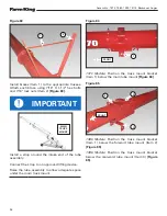
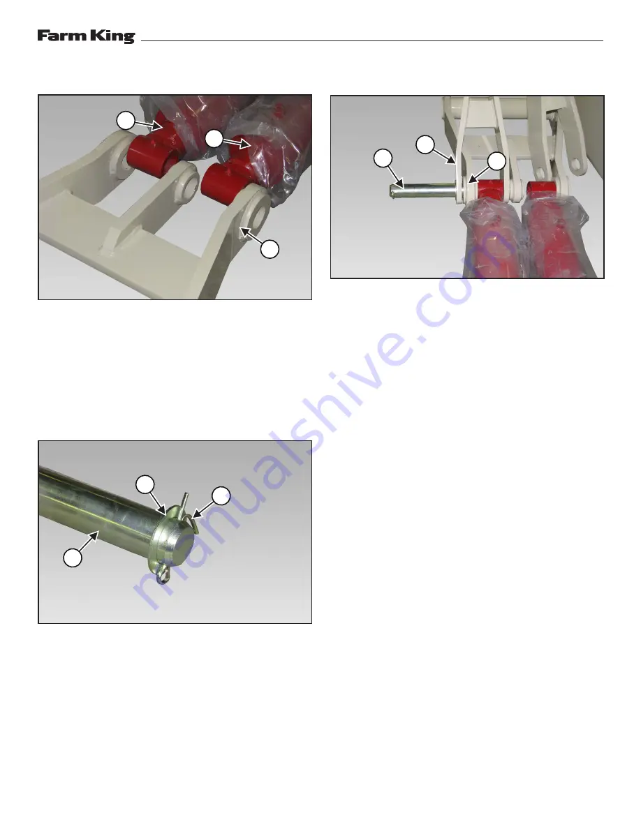
Figure 36
Raise the hydraulic cylinders (Item 1) and move
the two cylinders on the back side of the link (Item
2). Lower the cylinders to the ground and remove
the chain or strap
[Figure 36]
.
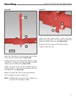
Align the two rod ends of the cylinders with the
link (with grease zerks facing up).
Figure 37
Install one 2” narrow rim washer (Item 1) and one
5/16” x 3” cotter pin (Item 2) onto the 2” x 18-7/8”
lift pin rod (Item 3)
[Figure 37]
.
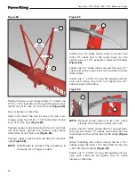
Figure 38
Place the left yoke arm (Item 1) on the outside of
the link (Item 2). Position cylinder inside the link
and opposite side of the yoke arm
[Figure 38]
.
Install the lift pin rod (Item 3) through the left yoke
arm, link and cylinder (stop when the pin enters
the center mount of the link)
[Figure 38]
.
2
2
1
3
1
3
1
1
2
Summary of Contents for 1370
Page 1: ...062019 FK429 ASSEMBLY MANUAL BACKSAVER AUGER Models 1370 1385 1395 13114...
Page 2: ......
Page 92: ...Assembly 1370 1385 1395 13114 Backsaver Auger 90...
Page 93: ......


