Assembly - 1370, 1385, 1395, 13114 Backsaver Auger
14
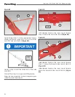
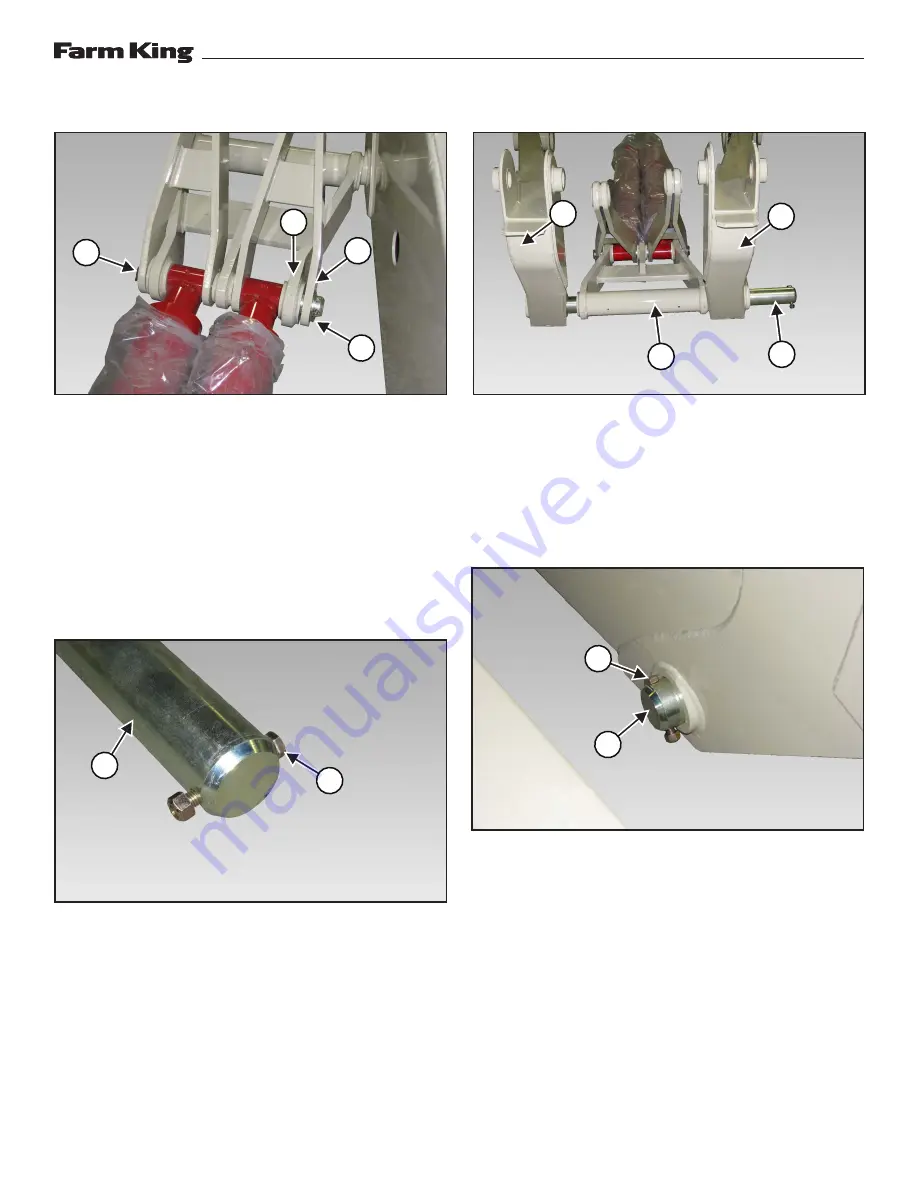
Figure 39
Place the right yoke arm (Item 1) on the outside of
the link (Item 2). Position cylinder inside the link
and opposite side of the yoke arm
[Figure 39]
.
Install the lift pin rod (Item 3) through the right
yoke arm, cylinder and link
[Figure 39]
.
Install one 2” narrow rim washer (Item 4) and
one 5/16” x 3” cotter pin to secure the yoke arms,
cylinders and link together
[Figure 39]
.
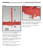
Figure 40
Install one 1/2” x 3-1/2” bolt (Item 1) through one
end of the 2 3/4” x 39” connecting yoke pin (Item
2), then install one 1/2” lock nut onto the bolt
[Figure 40]
.
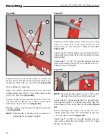
Figure 41
Align the RH lower lift arm (Item 1), link (Item 2)
and LH lower lift arm (Item 3)
[Figure 41]
.
Install the 2-3/4” x 39” connecting yoke pin (Item
4) through the LH lower lift arm, link and RH lower
lift arm
[Figure 41]
.
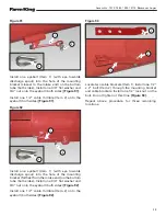
Figure 42
Install one 1/2” x 3-1/2” bolt (Item 1) through one
end of the 2-3/4” x 39” connecting yoke pin (Item
2), then install one 1/2” lock nut onto the bolt
[Figure 42]
.
3
2
4
1
1
2
4
3
1
1
1
2
Summary of Contents for 1370
Page 1: ...062019 FK429 ASSEMBLY MANUAL BACKSAVER AUGER Models 1370 1385 1395 13114...
Page 2: ......
Page 92: ...Assembly 1370 1385 1395 13114 Backsaver Auger 90...
Page 93: ......


