Assembly - 1370, 1385, 1395, 13114 Backsaver Auger
23
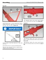
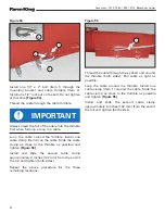
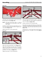
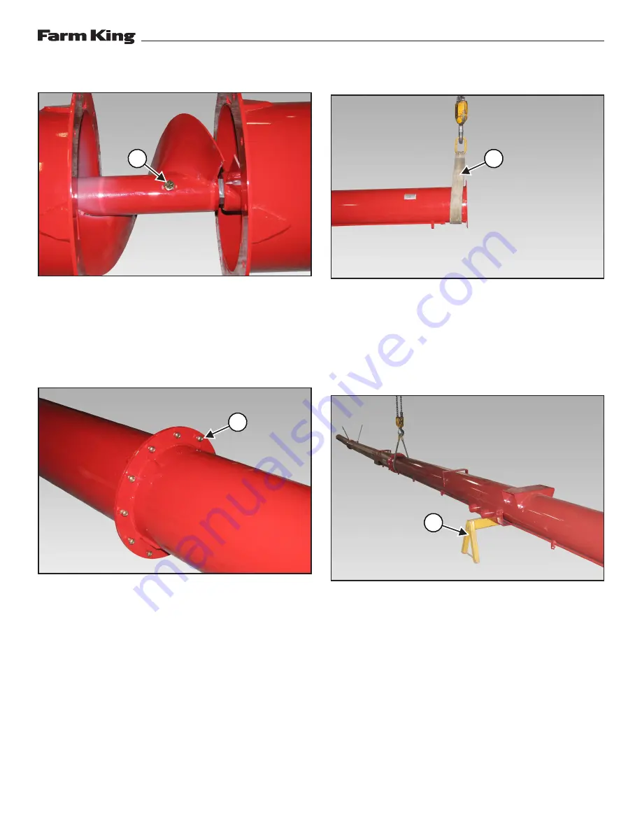
Figure 71
Slide the flighting from the center tube forward
onto the connecting shaft. Apply thread locker to
the bolt threads, install one 1/2” x 4” Gr. 8 bolt
(Item 1) and 1/2” lock nut. Tighten bolt and lock nut
[Figure 71]
.
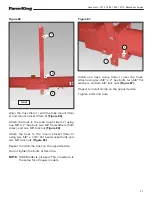
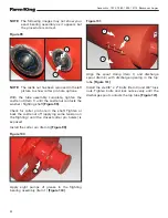
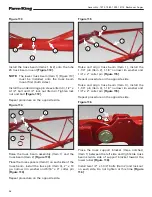
Figure 72
Slide the top and center tubes together until the
mounting flanges contact each other
[Figure 72]
.
Install 7/16” x 1-1/4” bolts (Item 1) through the
tube flanges. Install one 7/16” lock nut on each
bolt. Tighten bolts and lock nuts (top bolt first,
then bottom bolt
[Figure 72]
.
Repeat the procedure for connecting remaining
tube sections.
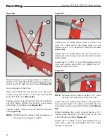
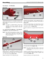
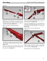
Figure 73
Install a strap (Item 1) around the end of the
bottom tube
[Figure 73]
.
NOTE:
Use a second strap and lifting device
on tube #3 when lifting the 13114 auger
assembly.
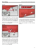
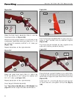
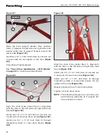
Figure 74
Raise the tube assembly and place a support stand
(Item 1) under the tube, lower the tube onto the
support stand
[Figure 74]
.
Remove strap.
1
1
1
1
Summary of Contents for 1370
Page 1: ...062019 FK429 ASSEMBLY MANUAL BACKSAVER AUGER Models 1370 1385 1395 13114...
Page 2: ......
Page 92: ...Assembly 1370 1385 1395 13114 Backsaver Auger 90...
Page 93: ......


