Assembly - 1370, 1385, 1395, 13114 Backsaver Auger
31
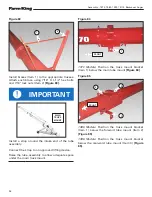
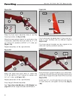
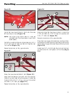
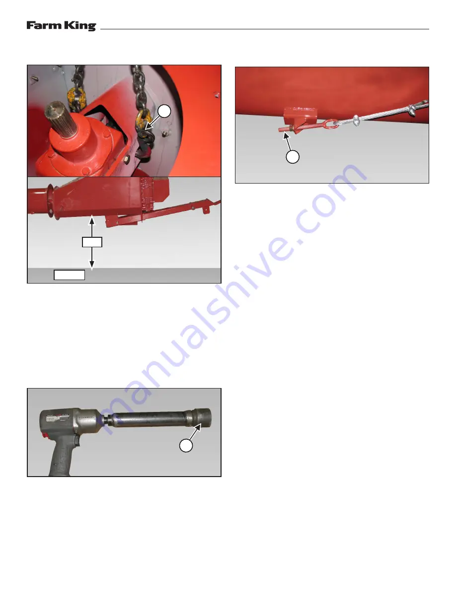
Figure 96
Install chains (Item 1) onto the input box gearbox
mounting bracket
[Figure 96]
.
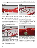
Raise the intake auger / tube assembly
approximately 4 ft. (1.22 m) off the ground.
Remove support stand from under the tube
assembly.
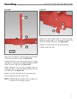
Figure 97
Place a mark (Item 1) on the cable tightening tool.
This will help to tighten the cables evenly
[Figure
97]
.
Count the revolutions as the tool is turning while
tightening.
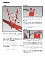
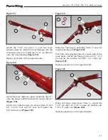
Figure 98
NOTE:
Cable lengths may vary. The following is a
starting point and cables may need to be
tightened more or loosened depending on
the cable length.
Tighten the long cable until there is approximately
3 - 4 inches (76 - 102 mm) of exposed threads (Item
1) on the eyebolt
[Figure 98]
.
Repeat tightening procedure for the remaining
cables.
NOTE:
Tighten short cables less than the longer
cables.
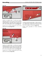
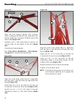
Lower the input box / tube assembly to the ground.
With the input box / tube assembly on the ground,
the discharge spout end of the tube assembly
should be bowed up (enough to install the
discharge spout).
Stand behind the intake end and look down the
full length of the tube assembly to verify the tube
is straight. Adjust short cables to straighten the
tube (left to right) as needed.
With the tube assembly straight and slightly bowed
up, tighten all the cable clamps and brackets on
the tube assembly.
1
1
1
GROUND
4 FT.
Summary of Contents for 1370
Page 1: ...062019 FK429 ASSEMBLY MANUAL BACKSAVER AUGER Models 1370 1385 1395 13114...
Page 2: ......
Page 92: ...Assembly 1370 1385 1395 13114 Backsaver Auger 90...
Page 93: ......


