Assembly - 1370, 1385, 1395, 13114 Backsaver Auger
39
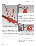
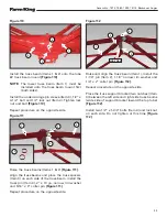
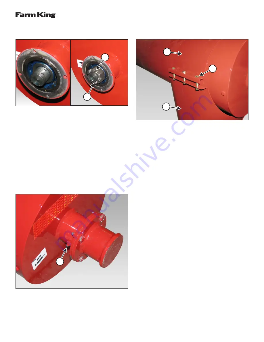
Figure 124
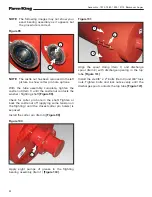
NOTE:
The castle nut has been removed in the left
picture to show cotter pin hole options.
With the tube assembly complete, tighten the
castle nut (Item 1) until the castle nut contacts the
washer / flighting shaft (Item 2)
[Figure 124]
.
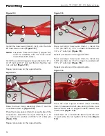
Check for cotter pin hole in the shaft. Tighten or
back the castle nut off (applying some tension on
the flighting) until the closest cotter pin hole(s) is
exposed.
Install the cotter pin.
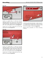
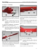
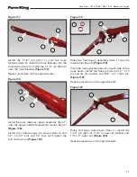
Figure 125
Apply eight pumps of grease to the flighting
bearing assembly (Item 1)
[Figure 125]
.
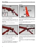
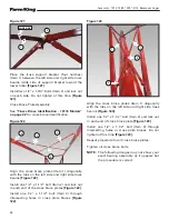
Figure 126
Align the spout clamp (Item 1) and discharge
spout (Item 2) with discharge opening in the top
tube
[Figure 126]
.
Install the six 3/8” x 2” bolts (Item 3) and 3/8” lock
nuts. Tighten bolts and lock nuts evenly until the
discharge spout contacts the top tube
[Figure 126]
.
2
1
2
1
3
1
Summary of Contents for 1370
Page 1: ...062019 FK429 ASSEMBLY MANUAL BACKSAVER AUGER Models 1370 1385 1395 13114...
Page 2: ......
Page 92: ...Assembly 1370 1385 1395 13114 Backsaver Auger 90...
Page 93: ......


