
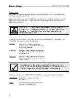


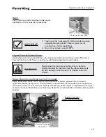

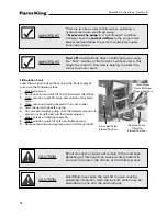
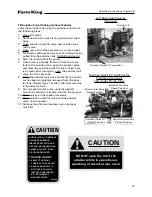
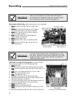
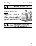

IMPORTANT
Check machine thoroughly for screws, bolts, fittings,
etc., which may have come loose during transport or
operation.
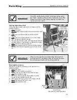
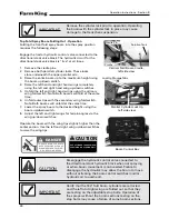
CAUTION
Prior to loading with chemical, the operator needs to
test the sprayer with water only to ensure the system
is intact prior to putting chemical into the system. Test
to verify application at the desired rate and all compo-
nents work correctly.
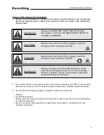
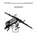
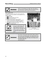
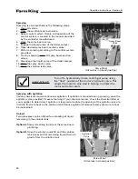
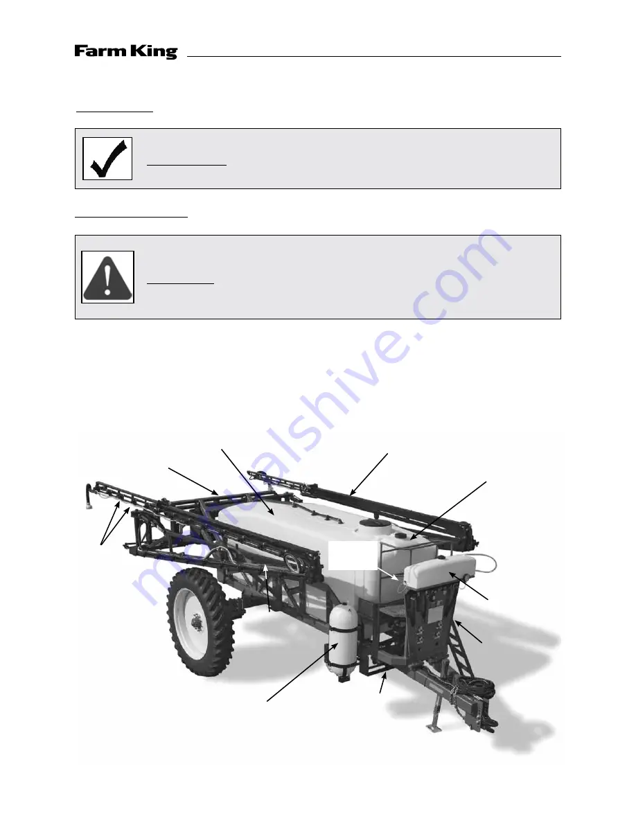
Inspect Unit
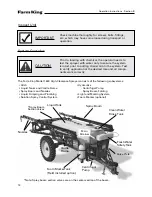
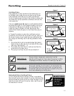
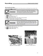
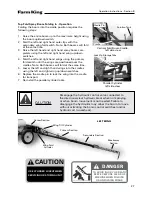
System Overview
The Farm King Model 1600 High-Clearance Sprayer consists of the following subsystems:
• Hitch
• Liquid Tanks and Cradle Frame
• Spray Boom and Nozzles
• Liquid Pumping and Plumbing
• Solution Spray Control System
• Hydraulics
- Centrifugal Pump
- Spray Boom Folding
• Light and Marking System
• Foam Marker (optional)
Nozzles
Liquid Tank
Spray Boom
*Spray Boom
Section Valves
Fresh Water
Safety Tank
Main
Strainer
Centrifugal
Pump
Valve Plate
Cradle
Frame
Foam Marker Tank
(Field installed option)
Clean Water
Rinse Tank
Operation Instructions - Section B
*Note: Spray boom section valves are on the center section of the boom.
14
Summary of Contents for 1600
Page 1: ...Operator and Parts Manual 1600 High Clearance Sprayer 04 2010 SXL 26030 ...
Page 5: ...Safety Instruction Section A 5 ...
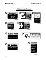
Page 11: ...Safety Decal Placement Safety Instructions Section A 11 ...
Page 12: ...Notes Safety Instructions Section A 12 ...
Page 13: ...Operation Instructions Section B 13 ...
Page 29: ...Connection Startup Section C 29 ...
Page 38: ...Connection Startup Section C Notes 38 ...
Page 39: ...Storage Section D 39 ...
Page 43: ...Maintenance Service Troubleshooting Section E 43 ...
Page 50: ...Maintenance Service Troubleshooting Section E Notes 50 ...
Page 51: ...Parts Schematics Section F 51 ...
Page 52: ...19 Description Decal Placement Parts Schematics Section F 52 ...
Page 54: ...Description Trailer Sprayer Light Kit Assembly Parts Schematics Section F 54 ...
Page 56: ...Description Frame Assembly Parts Schematics Section F 56 ...
Page 58: ...Description Drawbar Assembly Parts Schematics Section F 58 ...
Page 60: ...Description 10 Bolt Adjustable Axle Assembly Parts Schematics Section F 60 ...
Page 62: ...Description Cradle Assembly Parts Schematics Section F 62 ...
Page 64: ...Description Tank Spreader and Sight Gauge Parts Schematics Section F 64 ...
Page 66: ...Parts Schematics Section F Description Fold Over the Top Boom Center Section Assembly 66 ...
Page 68: ...Description Fold Boom Primary Section Assembly Parts Schematics Section F 68 ...
Page 70: ...Description Fold Boom Secondary Breakaway Assembly Parts Schematics Section F 70 ...
Page 72: ...Parts Schematics Section F Notes 72 ...
Page 74: ...Description Sprayer Hydraulic Routing Parts Schematics Section F 74 ...
Page 76: ...Description Fold Over The Top Boom Hydraulic Valve Breakdown Parts Schematics Section F 76 ...
Page 79: ...Parts Schematics Section F Notes 79 ...
Page 82: ...Description Spray Boom Cylinder Assembly Parts Schematics Section F 82 ...
Page 84: ...Description Boom Rephasing Cylinder Assembly Parts Schematics Section F 84 ...
Page 86: ...Description Pump Plumbing Parts Schematics Section F 86 ...
Page 88: ...Parts Schematics Section F Description Tank Plumbing 88 ...
Page 90: ...Description Raven Control Plumbing Parts Schematics Section F 90 ...
Page 93: ...Parts Schematics Section F Notes 93 ...
Page 94: ...Description Valve Mounting 94 Parts Schematics Section F ...
Page 96: ...Description Fold Over the Top Boom Plumbing Kit Parts Schematics Section F 96 ...
Page 98: ...Description Manual Fence Row Plumbing Parts Schematics Section F 98 ...
Page 100: ...Description Eductor Assembly Parts Schematics Section F 100 ...
Page 103: ...Warranty Section G 103 ...