

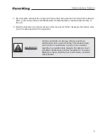


WARNING
004774
KEEP HANDS AND
BODY AWAY FROM
AREAS WHICH
EJECT FLUIDS UNDER
HIGH PRESSURE
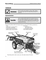
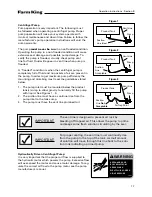
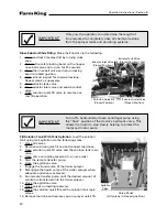
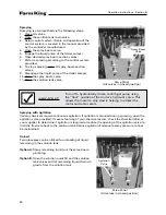
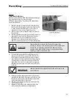
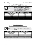
Figure 1
Vent Line
Product Tank
Pump
Suction
Line Ideal
Suction
Line
Acceptable
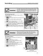
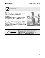
Figure 2
Vent Line
Product Tank
Pump
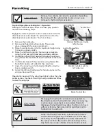
Figure 3
Vent Line
Product Tank
Pump
Suction
Line
Not
Acceptable
Air Trap Point
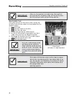
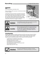
IMPORTANT
The vent line is designed to prevent air lock by
bleeding off trapped air. This allows the pump to prime
and keeps some fresh solution circulating by the seal.
IMPORTANT
For proper venting, the vent line must continually rise
from the pump to the top of the tank. A small amount
of solution will move through this line back to the solu-
tion tank indicating a primed pump.
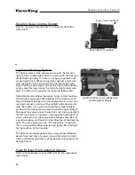
Centrifugal Pump
Pump operation is very important. The following must
be followed when operating a centrifugal pump. Proper
pump operation will make your system operate with
minimal maintenance and down time. Failure to follow the
manufacturer’s pump operation instructions will void the
pump warranty.
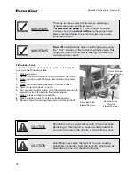
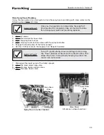
The pump
must never be run
in a non-flooded condition.
Operating the pump in a non-flooded condition will cause
extensive seal damage and possible pump damage. To
verify the pump is flooded, visually check pump vent
line for fluid. Fluid will appear in vent line when pump is
flooded.
A ”flooded” condition is when the centrifugal pump is
completely full of fluid and no pockets of air are present in
the pump. In order to get maximum pump efficiency the
mounting and plumbing must meet the guidelines stated
below.
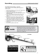
1. The pump inlet must be mounted below the product
tank(s) sump to allow gravity to naturally fill the pump
with liquid. See Figures 1 - 3.
2. The suction line must have a continual rise from the
pump inlet to the tank sump.
3. The pump must have the vent line plumbed to it.
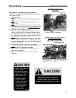
Hydraulically Driven Centrifugal Pump:
It is very important that the proper oil flow is supplied to
the hydraulic motor which powers the pump. Excessive flow
will over-speed the motor and cause motor damage. To reg-
ulate the correct oil flow to the pump motor see the pump
manufacturer’s manual.
Operation Instructions - Section B
17
Summary of Contents for 1600
Page 1: ...Operator and Parts Manual 1600 High Clearance Sprayer 04 2010 SXL 26030 ...
Page 5: ...Safety Instruction Section A 5 ...
Page 11: ...Safety Decal Placement Safety Instructions Section A 11 ...
Page 12: ...Notes Safety Instructions Section A 12 ...
Page 13: ...Operation Instructions Section B 13 ...
Page 29: ...Connection Startup Section C 29 ...
Page 38: ...Connection Startup Section C Notes 38 ...
Page 39: ...Storage Section D 39 ...
Page 43: ...Maintenance Service Troubleshooting Section E 43 ...
Page 50: ...Maintenance Service Troubleshooting Section E Notes 50 ...
Page 51: ...Parts Schematics Section F 51 ...
Page 52: ...19 Description Decal Placement Parts Schematics Section F 52 ...
Page 54: ...Description Trailer Sprayer Light Kit Assembly Parts Schematics Section F 54 ...
Page 56: ...Description Frame Assembly Parts Schematics Section F 56 ...
Page 58: ...Description Drawbar Assembly Parts Schematics Section F 58 ...
Page 60: ...Description 10 Bolt Adjustable Axle Assembly Parts Schematics Section F 60 ...
Page 62: ...Description Cradle Assembly Parts Schematics Section F 62 ...
Page 64: ...Description Tank Spreader and Sight Gauge Parts Schematics Section F 64 ...
Page 66: ...Parts Schematics Section F Description Fold Over the Top Boom Center Section Assembly 66 ...
Page 68: ...Description Fold Boom Primary Section Assembly Parts Schematics Section F 68 ...
Page 70: ...Description Fold Boom Secondary Breakaway Assembly Parts Schematics Section F 70 ...
Page 72: ...Parts Schematics Section F Notes 72 ...
Page 74: ...Description Sprayer Hydraulic Routing Parts Schematics Section F 74 ...
Page 76: ...Description Fold Over The Top Boom Hydraulic Valve Breakdown Parts Schematics Section F 76 ...
Page 79: ...Parts Schematics Section F Notes 79 ...
Page 82: ...Description Spray Boom Cylinder Assembly Parts Schematics Section F 82 ...
Page 84: ...Description Boom Rephasing Cylinder Assembly Parts Schematics Section F 84 ...
Page 86: ...Description Pump Plumbing Parts Schematics Section F 86 ...
Page 88: ...Parts Schematics Section F Description Tank Plumbing 88 ...
Page 90: ...Description Raven Control Plumbing Parts Schematics Section F 90 ...
Page 93: ...Parts Schematics Section F Notes 93 ...
Page 94: ...Description Valve Mounting 94 Parts Schematics Section F ...
Page 96: ...Description Fold Over the Top Boom Plumbing Kit Parts Schematics Section F 96 ...
Page 98: ...Description Manual Fence Row Plumbing Parts Schematics Section F 98 ...
Page 100: ...Description Eductor Assembly Parts Schematics Section F 100 ...
Page 103: ...Warranty Section G 103 ...


