background image

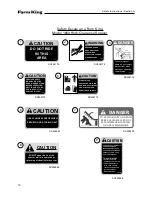
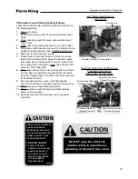
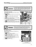
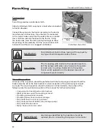
DO NOT open the lid of the

eductor while in operation as

splashing of chemical may occur.

CAUTION

CAUTION

AGRICULTURAL CHEMICALS
CAN BE DANGEROUS.
IMPROPER SELECTION OR
USE CAN INJURE PERSONS,
ANIMALS, PLANTS, SOILS
OR OTHER PROPERTY.

TO AVOID INJURY

1. SELECT THE RIGHT
  CHEMICAL FOR THE JOB.
2. HANDLE AND APPLY IT
  WITH CARE. FOLLOW
  INSTRUCTIONS ISSUED
  BY THE CHEMICAL
  MANUFACTURER.

002438

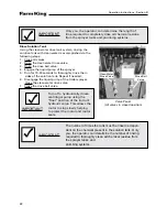
Fill Solution Tank, Utilizing Optional Eductor 

Load the solution tank using the optional eductor via 
the following steps:
1.  Close all valves.
2.  Remove solution quick fill cap and connect load 

hose.

3.  Open solution quick fill valve and solution tank 

main valve.

4.  Open valve on loading reservoir (i.e. nurse tank)
5.  Fill eductor with desired amount of chemical to be 

pulled into the solution tank. CLOSE Eductor Lid.

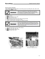
6.  Start the remote transfer pump.
7.  Once there is a steady flow rate from the nurse 

tank to the solution tank, open the eductor valve 
and close the solution quick fill valve. Once there 
is a steady flow rate again, open the eductor tank 
valve for 15-30 seconds.

8.  Close the eductor tank valve and verify the chemi-

cal has been completely removed from the educ-
tor tank. Repeat steps 7 and 8 if chemical remains 
in the eductor tank.

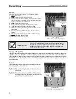
9.  Run remote transfer pump until the desired 

amount of solution is transferred into the sprayer.

10.  Close valves on the loading reservoir.
11.  Close solution quick fill valve and the eductor 

valve on the sprayer.

12.  Remove load line and replace cap on sprayer 

quick fill.

Operation Instructions - Section B

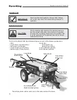
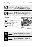
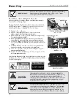
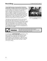
Solution Quick Fill Connection

Eductor Lid

Left Side View Eductor 

(Optional)

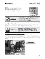
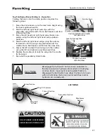
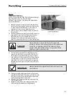
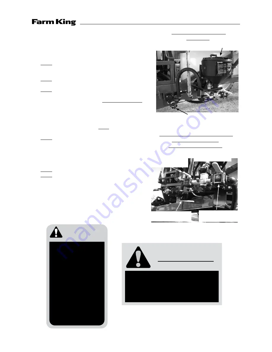
Solution Quick Fill and Eductor 

Plumbing (Optional)

Left Under Frame View

Eductor Inlet Valve

(Closed Position)

Solution Quick Fill

(Closed Position)

Eductor Outlet Valve

(Closed Position)

Eductor Tank Valve

(Closed Position)

19

Summary of Contents for 1600

Page 1: ...Operator and Parts Manual 1600 High Clearance Sprayer 04 2010 SXL 26030 ...

Page 2: ...ands safe and correct operating procedures Make sure unauthorized people do not operate or are not in the vicinity of the sprayer while it is in operation Maintain the sprayer in accordance with the maintenance schedule in this manual Furthermore as additional technology becomes available the owner is responsible for improving the safety and reliability of the system Fulfill all warranty obligatio...

Page 3: ...ctor While Filling 20 Fill SolutionTank withTank Agitation 20 Fill Clean Water RinseTank 21 Rinse Agitation System 21 Rinse SolutionTank 22 Rinse Spray Boom Plumbing 23 Spraying 24 Spraying with Agitation 24 Unload 24 Strainers 25 Hydraulics 25 Top Fold Spray Boom Folding Out 26 Top Fold Spray Boom Folding In 27 Solution Spray Control System 28 Light Marking System 28 Foam Marker 28 Connection Sta...

Page 4: ...arker 37 Vertical Fold Boom Adjustment 37 Storage Section D 39 Winterization 41 Maintenance Service Troubleshooting Section E 43 LiquidTank Frame and Plumbing 44 Hydraulics 45 Electrical Control System 45 Top Fold Spray Boom Lubrication 46 Wheel Lug NutTorque 47 BoltTorque Data 48 Troubleshooting 49 Parts Schematics Section F 51 Warranty Section G 103 4 ...

Page 5: ...Safety Instruction Section A 5 ...

Page 6: ...erious injury WARNING Indicates a potentially hazardous situation that if not avoided could result in death or serious injury CAUTION Indicates a potentially hazardous situation that if not avoided may result in minor or moderate injury In this manual the words IMPORTANT and NOTE are used to indicate the following IMPORTANT Highlights information that must be heeded NOTE A reminder of other relate...

Page 7: ...the following people to operate or repair this equipment Children Irresponsible persons People under the influence of alcohol medications or other drugs that can cause drowsiness or impaired judgement Persons unfamiliar with equipment or people who are careless or unfamiliar with safe operating procedures Warning Observe the IMPORTANT SAFETY INSTRUCTIONS listed below at all times THE BEST KIND OF ...

Page 8: ...ses as the square of the speed For example It will take twice as much distance to stop a unit traveling 15 mph as one going 10 mph and four times the distance at 20 mph more than eight times the distance at 25 mph Road surface will influence stopping distance Dry pavement is usually considerably better than gravel road Materials such as ice snow water oil or mud on the surface can greatly increase...

Page 9: ... further necessary information relat ing to the safe operation of the applicator Warning Certain chemicals can be very corrosive and may oxidize steel over a period of time This weakens steel parts and can cause failure to perform as intended resulting in possible safety hazards Periodically check all safety shields and structural members for corrosion Replace or repair anything that could cause a...

Page 10: ...UTION DO NOT RIDE IN THIS AREA 004773 CAUTION SERVICE PARTS MANUAL MUST BE READ UNDERSTOOD BEFORE OPERATING UNIT FAILURE TO DO COULD RESULT IN SERIOUS INJURY 004772 CAUTION USE CYLINDER LOCKUP WHEN SERVICING OR STORING UNIT CAUTION AGRICULTURAL CHEMICALS CAN BE DANGEROUS IMPROPER SELECTION OR USE CAN INJURE PERSONS ANIMALS PLANTS SOILS OR OTHER PROPERTY TO AVOID INJURY 1 SELECT THE RIGHT CHEMICAL ...

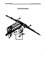
Page 11: ...Safety Decal Placement Safety Instructions Section A 11 ...

Page 12: ...Notes Safety Instructions Section A 12 ...

Page 13: ...Operation Instructions Section B 13 ...

Page 14: ...w The Farm King Model 1600 High Clearance Sprayer consists of the following subsystems Hitch Liquid Tanks and Cradle Frame Spray Boom and Nozzles Liquid Pumping and Plumbing Solution Spray Control System Hydraulics Centrifugal Pump Spray Boom Folding Light and Marking System Foam Marker optional Nozzles LiquidTank Spray Boom Spray Boom Section Valves Fresh Water SafetyTank Main Strainer Centrifuga...

Page 15: ...rning Never allow the clean water safety tank to become contaminated with chemical Use the clean water tank for skin and eye rinse in case of accidental chemical contact Spray Boom s and Nozzles not included Spray boom sizes are 60 to 90 vertical fold Hydraulic cylinders powered via the tractor hydraulics fold the Spray boom The required size of the nozzles is dependent on the application rate and...

Page 16: ...onfigured to provide for the following functions Fill Solution Tank Fill Solution Tank Utilizing Eductor if equipped Fill Solution Tank With Tank Agitation Fill Clean Water Rinse Tank Rinse Agitation System Rinse Solution Tank Rinse Spray Boom Plumbing Spray Unload Actual valve configuration will vary depending on options purchased Operation Instructions Section B Front Panel Hydraulically Driven ...

Page 17: ...s will void the pump warranty The pump must never be run in a non flooded condition Operating the pump in a non flooded condition will cause extensive seal damage and possible pump damage To verify the pump is flooded visually check pump vent line for fluid Fluid will appear in vent line when pump is flooded A flooded condition is when the centrifugal pump is completely full of fluid and no pocket...

Page 18: ...solution quick fill valve and solution tank main valve 4 Open valve on loading reservoir i e nurse tank 5 Start the remote transfer pump 6 Run remote transfer pump until the desired amount of solution is transferred into the trailer sprayer 7 Close valves on loading reservoir 8 Close solution quick fill valve on trailer sprayer 9 Remove load line and replace cap on trailer quick fill Caution Small...

Page 19: ...ote transfer pump 7 Once there is a steady flow rate from the nurse tank to the solution tank open the eductor valve and close the solution quick fill valve Once there is a steady flow rate again open the eductor tank valve for 15 30 seconds 8 Close the eductor tank valve and verify the chemi cal has been completely removed from the educ tor tank Repeat steps 7 and 8 if chemical remains in the edu...

Page 20: ...al fill operation Fill Solution Tank With Tank Agitation Load the solution tank using tank agitation via the following steps 1 Close all valves 2 Remove solution quick fill cap and connect load hose 3 Open solution quick fill valve and the solution tank main valve 4 Open valve on loading reservoir i e nurse tank 5 Start the remote transfer pump 6 Open the agitation valve 7 Engage the liquid pump o...

Page 21: ...ater quick fill valve on trailer sprayer Remove load line and replace cap on trailer quick fill Important Only you the operator can determine the length of time required to completely rinse all chemical residue from the sprayer tanks and plumbing systems Operation Instructions Section B Valve Panel All valves in closed position Clean Water Rinse Valve Agitation Valve Solution Quick Fill Valve Clos...

Page 22: ...nk with clean water is accomplished via the following steps 1 Close all valves 2 Open the clean water rinse valve 3 Open the rinse ball valve 4 Engage the liquid pump of the sprayer 5 Run for 15 30 seconds to thoroughly rinse the in sides of the solution tank Repeat if needed 6 Disengage the liquid pump of the trailer sprayer Close the clean water rinse valve 7 Close the rinse ball valve Important...

Page 23: ...ctor s hydraulic valve This allows the motor to stop slowly helping to protect the motor and motor seals Important Only you the operator can determine the length of time required to completely rinse all chemical residue from the sprayer tanks and plumbing systems Operation Instructions Section B Valve Panel All valves in closed position Clean Water Rinse Valve Spray Boom Valve 6 Run for 15 30 seco...

Page 24: ...or to stop slowly helping to protect the motor and motor seals Spraying with Agitation Certain chemicals require continuous agitation If agitation is required during spraying open the agitation valve provided If severe foaming of your chemical occurs check the chemical label or your supplier to determine if agitation is required or reduce the opening of the agitation valve to limit the flow rate b...

Page 25: ... fold operations are powered by the tractor hydraulics A pressure and return line for the liquid pump and a pressure and return line for the boom fold cylinders are located near the hitch of the sprayer A minimum requirement of 25 absolute micron filtration should be incorporated into the tractor hydraulics to assure adequate filtration of the oil supplied to the trailer sprayer components Importa...

Page 26: ...ooms will fold at the same time 6 Unfold outer tips with the secondary wing fold switch Note Both booms will unfold at the same time 7 Lower the spray boom to the desired height using the boom up down switch 8 Adjust the left and right wings for terrain angles via the wing up down switches Operate the boom with the wing tips slightly higher than the center section Use the left and right wing up do...

Page 27: ...t and right hand wings using the primary fold switch until the wings are positioned over the cradles Note Both booms will fold at the same time 5 Lower the left and right hand wings into the cradles using the left and right wing up down switches 6 Replace the cradle pin to lock the wing into the cradle for transport 7 Re install the parallel cylinder locks Caution Disengage the hydraulic control v...

Page 28: ...t the red taillights will be lit on the implement In a turn the red high intensity portion of the taillight will come on As with the amber in a right turn the left red high intensity portion of the taillight will remain on and the right taillight flashes at the same rate as the tractor s red turn signal light If a left turn signal is turned on the opposite takes place In a turn situation this ligh...

Page 29: ...Connection Startup Section C 29 ...

Page 30: ... set or the tires blocked A visual inspection of the entire sprayer should be made The visual inspection should include but not be limited to the review of the following see the maintenance section of this manual for further instructions Corrosion of all metal parts and structure Weld joints are sound no cracking or tears Plumbing connections are solid Plumbing hoses have no visual damage Poly tan...

Page 31: ...should be moved with the aid of a floor jack or equivalent lifting system Loosen and remove the two bolts that hold the spindle hub assembly to the axle sub frame Slide the assembly in or out to the desired row spacing Replace the bolts and nuts with new bolts and locknuts 5 Tighten all axle adjustment bolts to the torque specified in Section E Replace any bolts or nuts that have signs of physical...

Page 32: ...tom of boom frame Vertical Fold Spray Boom Tire Weight Capacities 8 MPH Operating Speed Vertical Fold Spray Boom Tire Weight Capacities 20 MPH Transport Speed Maximum Solution Tank Capacity in Gallons at 20 MPH with 380 90R46 Tires Solution Weight Per Gallon 1600 Gallon Tank 8 3 lb gal Water 1600 10 0 lb gal 1600 12 0 lb gal 1600 14 0 lb gal 1378 16 0 lb gal 1206 Static Load Boom Height Minimum 28...

Page 33: ...ifugal pump Make sure the hydraulic flow from your tractor does not exceed these specifications causing the pump to over speed Over speeding will decrease the motor seal life Connect the hydraulically driven pump to a tractor hydraulic circuit with a float position Use the float position to turn off the hydraulic pump to protect the hydraulic seals For tractors with an open hydraulic system connec...

Page 34: ... the majority of closed center hydraulic systems In this configuration the manifold does not allow the hydraulic oil a path back to the return side of the manifold when no boom functions are needed This configuration counts on the tractor s hydraulic system to turn off the flow of hydraulic oil to the manifold when no boom functions are needed Important Not configuring the directional stack hydrau...

Page 35: ...schematic in Section F for information on which connection lead operates the dump valve 5 Place the plug in the port in the left side of the manifold where you took out the dump cartridge 6 Torque all fittings to the specifications given on the directional stack schematic in Section F Directional Stack Valve Block Control Box Mounting 1 Mount the directional stack control box to the top of the sol...

Page 36: ... sensor and connect it to the solution controller according to the speed sensor and spray controller manufacturer s instructions Correct connection of the speed sensor flow meter control valve to the console should be made according to control manufacturer s instructions Calibration of the speed sensor is necessary to ensure accurate readings Calibrate the speed sensor according to the manufacture...

Page 37: ... compressor assembly to the frame of the sprayer Refer to the Foam Marker Operations Manual SXL 24121 for specific installation and setup instructions Vertical Fold Boom Adjustment Boom and Parallel Arm Lubrication The boom will follow the movement of the frame more if the boom is not allowed to move independently Refer to Section E of this manual for lubrication points on the boom and parallel ar...

Page 38: ...Connection Startup Section C Notes 38 ...

Page 39: ...Storage Section D 39 ...

Page 40: ... Remove and clean nozzles Store inside with other nozzles 8 Check for loose hardware and fittings and tighten accordingly 9 Replace all caps tank lids and plug nozzle outlets prior to storage 10 Poly tanks can become damaged when subjected to direct sunlight For longer life of this system it is best to store it in a cool dry location or drape with a sun protective tarp 11 Store sprayer with booms ...

Page 41: ...ater from the clean water rinse tank d Remove in line strainer bowls and dump out water reinstall the strainers e Remove the plug from the bottom of the pump drain and reinstall the plug f Raise the booms and at the bottom end of the plumbing of each boom section remove a diaphragm check valve to drain the boom Replace the diaphragm check valve 3 Begin the process of protecting the plumbing with t...

Page 42: ...ole has now been told that the sprayer is traveling at 5 mph v Upon the completion of the winterization the test speed can be cancelled by repeating steps one and two then enter 0 in step three instead of 5 and 0 c One at a time turn on each of the boom sections to allow the antifreeze solution to be pumped through the controls and the boom valves Run enough solution that the antifreeze begins to ...

Page 43: ...Maintenance Service Troubleshooting Section E 43 ...

Page 44: ...erify they tighten securely in place 6 Remove any debris from inside the tanks as they may become lodged in the strainer or pass into the pump 7 Clean strainer daily more frequently if your liquid supply is not free of debris 8 Inspect all welds and structural components for tears bends cracks or damage This unit operates in a corrosive environment Make certain corrosion is quickly removed and pai...

Page 45: ...plumbing schematic Important Failure to plumb the parallel cylinders correctly may cause damage to the Henschen suspension Electrical Control System Use of dielectric grease is strongly urged for all electrical wire connections All connections should be greased at the beginning of the season Poor electrical connections due to corrosion is the leading cause of failure of sprayer equipment in this e...

Page 46: ...itions Grease zerks are located at Wing attach point 4 total Item 1 Parallel linkage pins 8 total Item 2 Boom pivot 2 total Item 3 Secondary boom section fold hinge 2 total Item 4 Breakaway section pivot hinge 2 total Item 5 Primary section to boom pivots 2 total Item 6 1 4 5 2 3 6 1 Maintenance Service Troubleshooting Section E 46 ...

Page 47: ...ess on your Farm King Sprayer 1 Tighten lug nuts to correct torque specifications using a crisscross pattern Size Torque ft lb 3 4 16 UNF 250 265 5 8 18 Bolt 140 170 2 After tightening pull the Farm King 1600 High Clearance Sprayer approximately one 1 mile 3 Retighten lug nuts to correct torque specs 4 Use the sprayer stopping after three 3 hours and again after ten 10 hours to retighten lug nuts ...

Page 48: ...dial lines WARNING Mechanical fasteners must be torqued to recommended specifications during repair to prevent personal injury or equipment damage Maintenance Service Troubleshooting Section E GENERAL BOLT TORQUE DATA IN FT LB SAE GRADE 5 SAE GRADE 8 BOLT SIZE DRY LUB DRY LUB 1 4 20 8 6 12 9 1 4 28 9 7 13 10 5 16 18 17 13 25 18 5 16 24 19 14 25 20 3 8 16 30 23 45 35 3 8 24 35 25 50 40 7 16 14 50 3...

Page 49: ...en Bypass adjustment set improperly Adjust bypass screw on side of hydraulic motor to manufacturer s specifications Poor spray pattern nozzles dribble Nozzles too large Strainer clogged See nozzle supplier Clean strainer Spray atomizing and blowing around Nozzle too small Tractor speed too fast See nozzle supplier Reduce speed Spray streaming No uniform pattern Nozzle partially clogged Remove and ...

Page 50: ...Maintenance Service Troubleshooting Section E Notes 50 ...

Page 51: ...Parts Schematics Section F 51 ...

Page 52: ...19 Description Decal Placement Parts Schematics Section F 52 ...

Page 53: ...SX004774 Decal Warning Keep Hands Away 1 8 SX004776 Decal Danger Electrical Lines 1 9 SX004764 Decal 1 x 4 Clean Water 1 10 SX004766 Decal 1 x 4 Agitation 1 11 SX006907 Decal Sprayer Valve Chart 1 12 SX004772 Decal Caution Read Manual 1 13 SX004775 Decal caution Chemical Handling 1 14 SX004765 Decal 1 x 4 Spray Boom 1 15 SX004767 Decal 1 x 4 Rinse Ball 1 17 SX019779 Decal Farm King 1600 Left 1 18 ...

Page 54: ...Description Trailer Sprayer Light Kit Assembly Parts Schematics Section F 54 ...

Page 55: ... Harness 20 Tractor Implement 1 4 SX004560 Light Red Lamp 2 5 SX004561 Light Amber Lamp 2 6 SX006978 Turn Signal Module II 1 9 SXBH 050 125 2 Bolt 1 2 x 1 1 4 Hex Gr 2 4 10 SXLN 050 NI Locknut 1 2 Nylon Insert 4 13 SX17 5910 Reflector 2 x 9 Amber Night 4 14 SX17 5915 Reflector 2 x 9 Red Night 2 15 SX17 5920 Reflector 2 x 9 Orange Day 2 Parts Schematics Section F 55 ...

Page 56: ...Description Frame Assembly Parts Schematics Section F 56 ...

Page 57: ...8 ELHB x 3 8 HB 1 21 SXA1438 Hose Fitting 1 4 MPT x 3 8 HB 1 22 SXBH 025 250 5 Bolt 1 4 x 2 1 2 Hex Gr 5 2 23 SXBH 031 075 2 Bolt 5 16 x 3 4 Hex 2 24 SXBH 100 850 5 Bolt 1 x 8 1 2 Grade 5 4 25 SXBU031 100 175 U Bolt 5 16 x 1 x 1 3 4 Sq 2 26 SXBU038 200 300 U Bolt 3 8 x 2 x 3 Gr 2 Sq 2 30 SXHPC 210 Pin Clip 2 3 16 x 7 8 2 31 SXLN 025 NI Locknut 1 4 Nylon Insert 2 32 SXLN 031 NI Locknut 5 16 Nylon I...

Page 58: ...Description Drawbar Assembly Parts Schematics Section F 58 ...

Page 59: ... 1 2D SXVB91 Nut Clevis 1 3 SX004752 Jack stand Weld 1 4 SX006933 Chains Safety 1 5 SXBH 075 250 2 Bolt 3 4 x 2 1 2 Gr 5 12 6 SXBH 100 650 5 Bolt 1 x 6 1 2 Gr 5 2 7 SXLN 075 NI Locknut 3 4 Nylon Insert 12 8 SXLN 100 NI Locknut 1 Nylon Insert 2 9 SX004576 Pin Cotterless 1 2 x 3 1 2 1 Description Drawbar Assembly Parts Schematics Section F 59 ...

Page 60: ...Description 10 Bolt Adjustable Axle Assembly Parts Schematics Section F 60 ...

Page 61: ...2 SX910334 Outer Cup 1 13 SX905944 Cotter Pin Spindle 1 14 SX913632 Flat Washer Spindle 1 15 SX912969 Nut Spindle 1 1 4 12 1 16 SX905205 Bolt Dust Cap 4 17 SX909983 Dust Cap 1 18 SX913571 Wheel Nut 3 4 16 Flanged 10 19 SX017690 380 90R46 YR 1 20 SX017692C 380 90R46 CR 1 21 SX017689 380 90R46 YL 1 22 SX017691C 380 90R46 CL 1 23 SXBH 075 250 5 Bolt 3 4 x 2 1 2 Gr 5 4 24 SXBH 075 900 8 Bolt 3 4 x 9 G...

Page 62: ...Description Cradle Assembly Parts Schematics Section F 62 ...

Page 63: ...pping Screw 5 7 SX013402 Rod Wing Cradle Slide 1 8 SXPLI 031 250 Pin Linch Pin 5 16 x 2 1 2 1 9 SX013049 Tube Manual Storage 1 10 SX 64J Clamp 4 x 1 2 Stainless 2 11 SX014159 Manual Bracket Bent with Holes 1 12 SXBU031 150 350 U Bolt 5 16 x 1 1 2 x 3 1 2 Gr 2 2 13 SXLN 031 NI Locknut 5 16 Nylon Insert 4 Not shown Specify color Used on one side only Quantities listed are per side Description Cradle...

Page 64: ...Description Tank Spreader and Sight Gauge Parts Schematics Section F 64 ...

Page 65: ...ylon Insert Stainless 2 3 SX007666 Sleeve Tank Spreader Weld 1 4 SX007668 Shaft 1600 Tank Spreader 1 5 SX006216 Sight Gauge Weld 1 6 SXBH 038 125 2 Bolt 3 8 x 1 1 4 Gr 2 1 7 SXLN 038 NI Locknut 3 8 Nylon Insert 1 Not shown Specify color Description Tank Spreader and Sight Gauge Parts Schematics Section F 65 ...

Page 66: ...Parts Schematics Section F Description Fold Over the Top Boom Center Section Assembly 66 ...

Page 67: ...6 SX012096 Pin Main boom Pivot 1 17 SX012099 Wear Pad 570 Booms 2 18 SXBH 031 1150 5 Bolt 5 16 x 11 1 2 Grade 5 4 19 SXBH 031 300 5 Bolt 5 16 x 3 Grade 5 8 20 SXBH 038 150 5 Bolt 3 8 x 1 1 2 Grade 5 2 21 SXBH 038 300 5 Bolt 3 8 x 3 Grade 5 2 22 SXBH 050 450 5 Bolt 1 2 x 4 1 2 Grade 5 2 23 SXBH 050 800 5 Bolt 1 2 x 8 Grade 5 5 24 SXBT 075 300 5 Bolt Tap 3 4 x 3 Grade 5 2 25 SXBH 075 350 5 Bolt 3 4 ...

Page 68: ...Description Fold Boom Primary Section Assembly Parts Schematics Section F 68 ...

Page 69: ...y LH 1 3 SX012058 Plate Cylinder Wing Lift 2 4 SX012095 Pin Primary Mount 1 5 SXBH 038 150 5 Bolt 3 8 x 1 1 2 Hex Grade 5 1 6 SXBH 038 275 5 Bolt 3 8 x 2 3 4 Grade 5 1 8 SXBH 100 600 8 Bolt 1 x 6 Grade 8 1 10 SXLN 038 NI Locknut 3 8 Nylon Insert 1 11 SXLN 100 CL Locknut 1 Center Locknut 1 12 SXLW 038 Locknut 1 Center Locknut 1 13 SXPCL 100 300 1 x 3 Clevis Pin 5 Note Quantities are per side 69 ...

Page 70: ...Description Fold Boom Secondary Breakaway Assembly Parts Schematics Section F 70 ...

Page 71: ...3 SXBH 031 200 5 Bolt 5 16 x 2 Gr 5 1 14 SXBT 075 300 5 Bolt 3 4 x 3 Grade 5 2 15 SXBH 038 300 5 Bolt 3 8 x 3 Gr 5 Hex 3 16 SXFW 075 Flat washer 3 4 9 5 Per 2 17 SXLN 031 NI Locknut 5 16 Nylon Insert 1 18 SXLN 038 NI Locknut 3 8 Nylon Insert 3 19 SXNUT 050 J Nut 1 2 Jam Nut 2 20 SXNUT 075 J Nut 3 4 Jam Nut 4 21 SXFW 038 Flat washer 3 8 2 22 SXBH 050 450 5 Bolt 1 2 x 4 1 2 Gr 5 1 23 SXPCL 100 300 P...

Page 72: ...Parts Schematics Section F Notes 72 ...

Page 73: ...y R S 16 6 SX012044 Primary L S 16 6 SX011997 Secondary R S 13 9 SX011998 Secondary L S 13 9 SX012083 BKWY R S 8 6 SX012084 BKWY L S 8 6 2006 Model Year Prior 1600 SX011965 60 Vertical Fold Center Section 11 11 SX011953 SX011954 SX012043 Primary R S 16 6 SX012044 Primary L S 16 6 SX015759 Secondary R S 1 9 SX015760 Secondary L S 1 9 SX012115 BKWY R S 5 6 SX012116 BKWY L S 5 6 1600 SX011970 66 Vert...

Page 74: ...Description Sprayer Hydraulic Routing Parts Schematics Section F 74 ...

Page 75: ...trictor Elbow 2 17 SX004057 320 Hyd Hose 2 18 SX004050 34 Hyd Hose 1 19 SX007609 360 Hyd Hose 2 20 SX007475 34 Hyd Hose 1 2 Female JIC Swivel 1 21 SX210 127 Plug 6 Outlet Plug 2 22 SX210 038 Plug 8 Cartridge Port 2 23 SX6400 6 8R 06 Hyd ADPT Rest 8MORB 6MJIC 06 4 24 SX6405 8 8 Hyd Fitting 8MORB 8FPT 2 25 SX640370 Plug Vent 1 2 NPT 2 26 SX6602 6 Hyd Tee Run w Female Switch 3 27 SX9030 84 84 Hyd Hos...

Page 76: ...Description Fold Over The Top Boom Hydraulic Valve Breakdown Parts Schematics Section F 76 ...

Page 77: ... SX211 234 FTG CAP 6 MJ Red 8 7 SX232 050 Decal S N Silver 2 8 SX232 059 Decal Gold Black 1 5 x 5 1 9 SX253 022 Coil H F 6309412 W PS 12V 1 22A 4 10 SX253 028 Coil H F 6369412 W PS 12V 1 67A 6 11 SX270 093 Mani S14153 4 5Cir AL RV 1 12 SX273 008 Cart SV10 40 0 N 00 1 13 SX273 012 Cart CP10 20 1 14 SX273 017 Cart SV10 21 0 N 00 1 15 SX273 078 Cart H F RV10 22H 0 N 35 30 RFL Diff Area Pop 3000 PSI 2...

Page 78: ...Description Top Fold Boom 5 Bank Hydraulic Valve Bank Wiring Diagram Item Part Description Quantity 1 SX319 028 Fasse Control Block Wiring Harness 1 Parts Schematics Section F 78 ...

Page 79: ...Parts Schematics Section F Notes 79 ...

Page 80: ...Description Fold Over The Top Boom 5 Bank Hydraulic Switch Box Breakdown Parts Schematics Section F 80 ...

Page 81: ... Gray 5 16 SX255 006 TRM PO E NON INS 20 18GA 7 21 SX255 710 STR RLF Heyco 45 705 ID Hole Dia 1 115 1 22 SX259 005 SW TOG Grip Vinyl Red 187 1 23 SX259 015 SW TOG Grip Vinyl Blue 187 1 24 SX259 022 SW TOG Grip Vinyl Yel 187 1 25 SX259 023 SW TOG Grip Vinyl Grn 187 1 26 SX259 027 SW TOG Grip Vinyl Gry 187 1 27 SX304 358 Encl DRL MNTR 1 x 5 8 G1 x FUSEHOLDER 1 28 SX312 002 Encl Drill FP MNTR SW5 C00...

Page 82: ...Description Spray Boom Cylinder Assembly Parts Schematics Section F 82 ...

Page 83: ...8 SX135995 SX135995 Pin 4 9 SX498006 SX498006 Thread Lock Nylon 1 10 SX492652 SX492652 Rod Clevis 1 11 SX148390 SX148390 SC Sckt Set 3 8 UNC 1 12 SX128250 SX128250 Nut Hex Tie Rod 8 13 SX130560 SX130560 Nut Hex Cyl Rod 1 14 SX186562 SX186562 Plug 3 4 16 SOC HD 1 15 21 SX639558 SX639559 Seal Repair Kit 1 15 Seal 2 16 O Ring 2 17 Seal Hallite 1 18 O Ring 1 19 Seal NOK 1 20 Seal PTFF Piston Ring 1 21...

Page 84: ...Description Boom Rephasing Cylinder Assembly Parts Schematics Section F 84 ...

Page 85: ...6 SX492282 SX492282 Tie Rod 4 7 SX492650 SX492652 Rod Clevis 1 8 SX492660 SX492675 Clevis Cap 1 9 SX492661 SX492670 Rod Cap 1 10 SX493272 SX493580 Cylinder Rod 1 11 SX494727 SX494719 Piston 1 12 SX498066 SX498006 Thrd Lock Nylon 1 SX639557 SX639558 Seal Repair Kit 1 13 Seal PTFF Piston Ring 1 14 Seal Hallite 1 15 Seal 2 16 O Ring 2 17 O Ring 1 18 Seal NOK 1 19 Wear Ring 1 Not sold separately only ...

Page 86: ...Description Pump Plumbing Parts Schematics Section F 86 ...

Page 87: ...w 1 12 SX2404 8 8 Hyd Fitting 8 MJIC x 8 MNPT 1 13 SXBH 038 175 5 Bolt Hex 3 8 x 1 3 4 Gr 5 2 14 SXLN 038 NI Locknut 3 8 Nylon Insert 14 15 SXBH 038 100 5 Bolt Hex 3 8 x 1 Gr 5 6 16 SX013450 Weldment Pump Mount 1 17 SXFC220BJ Clamp Flange 2 FP 6 18 SXM220MPT Manifold 2 FP 1 19 SXBUR038 250 Bolt U 3 8 x 2 1 2 x 4 3 20 SXM220TEE Tee Flange 2 FP 2 21 SXM220BRB90 Hose Barb 2 FP FLG x 2 HB Elbow 1 22 S...

Page 88: ...Parts Schematics Section F Description Tank Plumbing 88 ...

Page 89: ...1 150 Black Rubber 35 10 SXSIGHT 34 Hose Sight Gauge 3 4 6 11 SX3371 0028 Jet Agitator High Cap 2 12 SXFC100BJ Clamp 1 FLG 4 13 SXHBT100 Tee HB 1 1 14 SX100G Gasket 1 FLG 4 15 SXHB 075 90 HB 3 4 HB x 3 4 MNPT EL 1 16 SX 16J Clamp 1 Hose 8 17 SX 12J Clamp 3 4 Hose 4 18 SXM100MPT Manifold 1 FLG 1 MNPT 1 19 SXMM3410 Reducing Nipple 1 to 3 4 2 20 SX2000 6 Rinse Nozzle 2 21 SXM100BRB90 Hose Barb 1 FLG ...

Page 90: ...Description Raven Control Plumbing Parts Schematics Section F 90 ...

Page 91: ... FLG x 1 1 2 HB Elbow 6 16 SX013439 Cable Valve Extension 17 SX006367 Cable Assembly 12 Valve 1 18 SXM200BRB90 Elbow Flange 2 x 2 HB 90 2 19 SXBC 025 075 2 Bolt 1 4 x 3 4 Carriage 16 20 SXNTF 025 Nut 1 4 20 Serrated Flange 16 21 SXM100BRB90 Hose Barb 1 FLG x 1 HB Elbow 2 22 SXMVT100CF Valve 1 FLG T Handle 2 23 SXM100CPG Coupler 1 FLG x 1 FLG 2 24 SXM100BRB Hose Barb 1 FLG x 1 HB 2 25 SX004557 Moun...

Page 92: ...gulating 1 45 SXLST150 B Strainer Bowl 2 1 46 SXLST150 G Strainer Gasket 2 1 47 SXLST1550 Strainer Screen 50 Mesh 1 48 SXLST150 H Strainer Head 2 1 49 SX013461 Plate Control Plumb Mnt 1 50 SXLN 031 NI Locknut 5 16 Nylon Insert 8 51 SXBH 031 062 5 Bolt Hex 5 16 x 5 8 Gr 5 6 52 SXLW 031 Washer Lock 5 16 6 53 SXFW 031 Washer Flat 5 16 6 54 SX6000 02Y Tank 9 Gallon Rinse 1 55 SX200972 Cover 3 1 2 1 56...

Page 93: ...Parts Schematics Section F Notes 93 ...

Page 94: ...Description Valve Mounting 94 Parts Schematics Section F ...

Page 95: ...9 SX16J Clamp 1 Hose 10 SXM100BRB90 Hose Barb Flange Elbow 1 11 SXFC100BJ Clamp 1 Flanged 12 SX100G Gasket 1 Flanged Valve 13 SXTBC225 Clamp T Bolt 1 14 SX012412 Hose 1 1 2 150 Black Rubber 15 SXBUR038 250 U Bolt 3 8 x 2 1 2 x 4 Round Zinc 16 SXLN 038 NI Locknut 3 8 Nylon Insert 17 SX013141 Weldment Hose Support 1 18 SX013470 Valve Boom Banjo w connection 19 SXBU050 300 450 Bolt U 1 2 x 3 x 4 1 2 ...

Page 96: ...Description Fold Over the Top Boom Plumbing Kit Parts Schematics Section F 96 ...

Page 97: ... Hose 1 150 Black Rubber 6 SXM100G Gasket 1 Manifold Valve 7 SXFC100BJ Clamp 1 8 SXM100BRB Hose Barb 1 Flange Straight 9 SXMLST100 50 Strainer T Line Flanged 10 SXQJ111SQ Clamp 1 1 4 QUick Clamp SQ 11 SXQJ363 750 1 Turret 3 Outlet 3 4 Elbow 12 SXQJ363 750 2 Turret 3 Outlet w 3 4 Tee Note Quantities are per side Quantities vary depending on boom length and nozzle spacing Parts Schematics Section F ...

Page 98: ...Description Manual Fence Row Plumbing Parts Schematics Section F 98 ...

Page 99: ...Female NPT Brass 1 6 SXHB 038 Hose Barb 3 8 MPT x 3 8 HB 1 7 SXHB 038 050 Hose Barb 3 8 MPT x 1 2 HB 1 8 SXHB 075 Hose Barb 3 4 MPT x 1 2 HB Poly 2 9 SXHB 075 050 90 Hose Barb Ell 3 4 MPT x 1 2 HBEL 1 10 SXQJ1 4T NYB QJ 1 4T QuickJet Body 1 11 SXTEE 075 Tee Poly 3 4 Female 1 12 SX000612 Hose 3 8 150 EPDM 13 SX000812 Hose 1 2 150 EPDM 14 SX 24J Clamp 1 1 2 x 1 2 Stainless 1 Note Quantities listed a...

Page 100: ...Description Eductor Assembly Parts Schematics Section F 100 ...

Page 101: ... EL 2 14 SX012012 Hose 1 1 4 150 EPDM 3 15 SX013142 Plate Hypro Eductor Mount 1 16 SX013488 Plate Frame Side Parallel 1 17 SXSBSE068 Latch Overcenter 2 18 SXBM 10 24 075 Bolt Mach 10 24 x 3 4 Hex 4 19 SX013489 Weldment Parallel w Lug 1 20 SX013492 Nut Push Closed End 3 8 Shaft 8 21 SX013493 Spring Gas 2 36 Stroke 80 Lb Force 1 22 SXNTF 031 Nut 5 16 Flange 2 23 SXBH 038 100 2 Bolt Hex 3 8 x 1 Gr 2 ...

Page 102: ...t 1 2 SX010442 Rod Adjustment 1 3 SX010443 Weldment Sensor Mount 1 4 SX171 C Screw TEK 410HSS Cad Plated 2 5 SX063 0159 982 Sensor Gear Tooth Speed 1 6 SX115 0159 018 Cable Speed Sensor 24 Ext Cable 1 7 SXBH 025 075 2 Bolt 1 4 x 3 4 Gr 2 1 8 SXLN 025 NI Locknut 1 4 Nylon Insert 1 9 SXSTS 025 038 Set Screw 1 4 x 3 8 Allen Hd 2 102 ...

Page 103: ...Warranty Section G 103 ...

Page 104: ..._________________________________________________________________ ____________________________________________________________________________________ ____________________________________________________________________________________ ____________________________________________________________________________________ _______________________________________________________________________________...

Page 105: ...mstances are component parts warranted against normal wear and tear There is no warranty on product pump seals product pump bearings rubber product hoses pressure gauges or other components that require replacement as part of normal maintenance Repair Parts Limited Warranty Farm King warrants genuine Farm King replacement parts purchased after the expiration of the Farm King Limited Warranty and u...

Page 106: ...OFTHE COMPONENTS AND PARTS COVERED BYTHIS WARRANTY AND NOT SPECIFICALLY PROVIDED FOR HEREIN TOTHE EXTENT PERMITTED BY LAW FARM KING DISCLAIMS ANY IMPLIED WARRANTIES OF MERCHANTABILITY AND FITNESS FOR A PARTICULAR PURPOSE ON ITS PRODUCTS COVERED HEREIN AND DISCLAIMS ANY RELIANCE BYTHE PURCHASER ON FARM KING S SKILL OR JUDGMENTTO SELECT OR FURNISH GOODS FOR ANY PARTICULAR PURPOSE THE PURCHASER S ONL...

Page 107: ...tract or on any other basis with respect to the subject equipment This limited warranty is subject to any existing conditions of supply which may directly affect Farm King s ability to obtain materials or manufacturer replacement parts Buhler Industries Inc reserves the right to make improvements in design or changes in specifications to its products at anytime without incurring any obligation to ...

Page 108: ...Buhler Industries Inc 1330 43rd Street NW Fargo ND USA 58102 Ph 701 282 7014 Fax 701 282 5865 E mail info buhler com www farm king com Equipment shown is subject to change without notice 2010 BuhlerTrading Inc Printed in U S A TSX BUI ...

Reviews: