


Connection & Startup - Section C
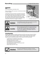
Axles
Adjustable Width Axles
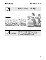
The Farm King Model 1600 High-Clearance Sprayer
has adjustable axles to accommodate
different row spacing. The axle width adjustment
procedure follows:
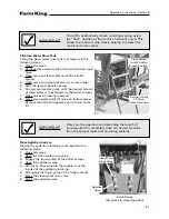
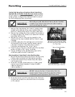
1. Secure sprayer on level ground, attached to a
tractor with the wheels chocked and the tractor
in park. Ensure that NO fore or aft rolling of
sprayer can occur when elevating a tire.
2. Using a jack, hoist or forklift, raise one tire off
the ground.
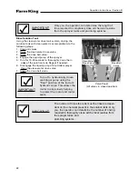
3. Secure elevated side with jack stands, braces, or
equivalent, ensuring that the sprayer cannot
fall while the tire and spindle are moved.
Damage to the sprayer and serious injury or
death to personnel can occur if the sprayer falls.
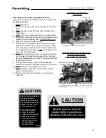
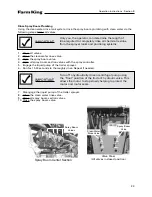
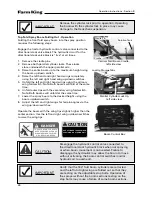
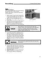
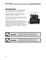
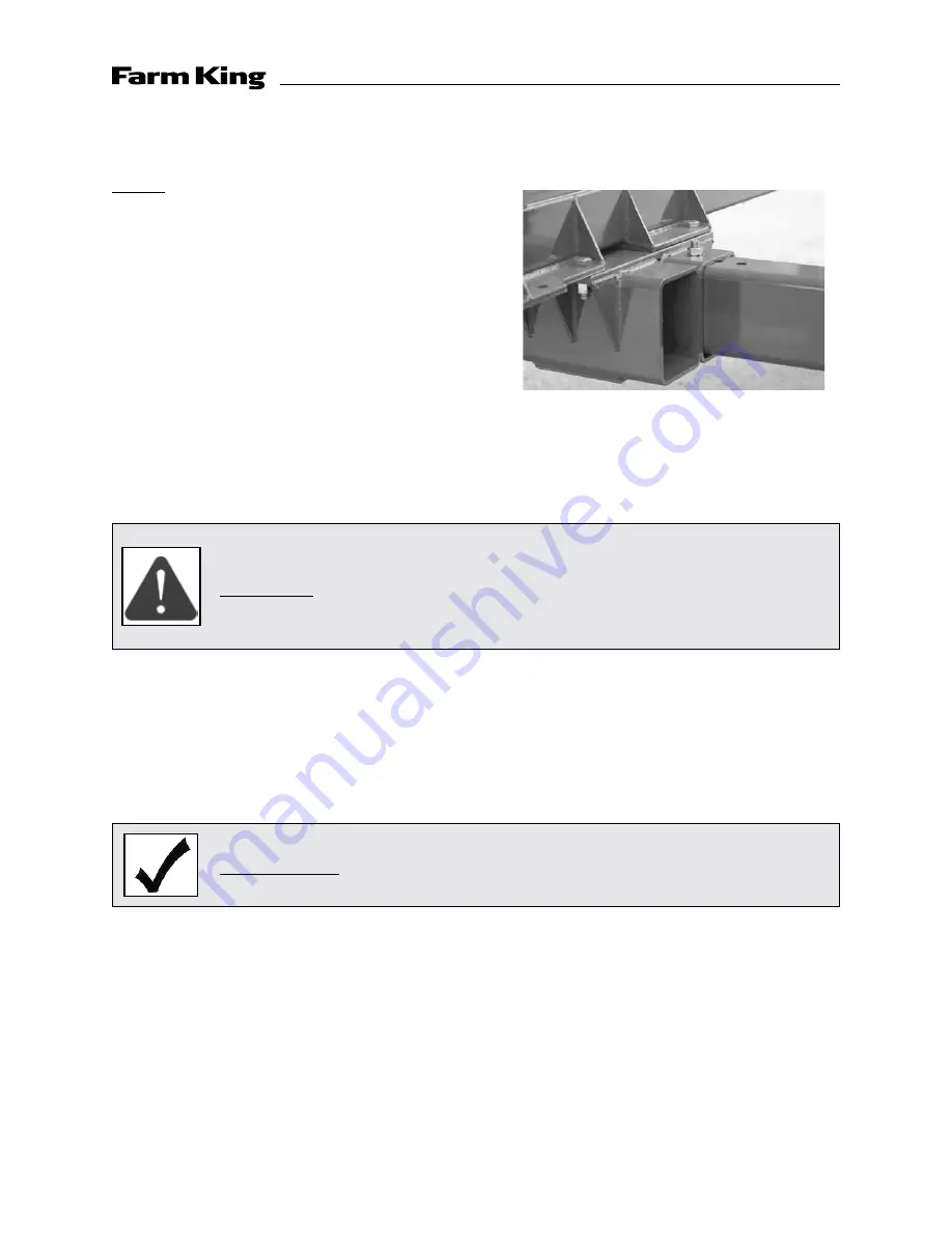
4. The spindle assembly/hub and wheel is very
heavy and should be moved with the aid of a
floor jack or equivalent lifting system. Loosen
and remove the two bolts that hold the spindle/
hub assembly to the axle sub-frame. Slide the
assembly in or out to the desired row spacing.
Replace the bolts and nuts with new bolts and
locknuts.
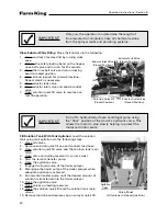
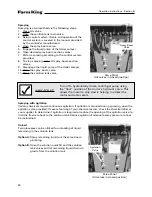
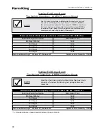
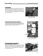
5. Tighten all axle adjustment bolts to the torque
specified in Section E. Replace any bolts or nuts
that have signs of physical damage, especially
noting damage due to corrosion.
6. Remove jack stands and braces and lower the
unit to the ground.
7. Repeat for the other side making certain the
same center line distance is maintained.
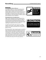
IMPORTANT
Always replace the adjustment bolts with new bolts
and locknuts.
DANGER
Never attempt to adjust the tire width unless the
sprayer is secure, and on level ground. The liquid tank
should be completely void of fluid. Always secure
sprayer with jack stands, braces or equivalent when
working under an elevated unit.
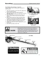
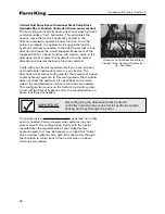
Axle Tube Weldment
31
Summary of Contents for 1600
Page 1: ...Operator and Parts Manual 1600 High Clearance Sprayer 04 2010 SXL 26030 ...
Page 5: ...Safety Instruction Section A 5 ...
Page 11: ...Safety Decal Placement Safety Instructions Section A 11 ...
Page 12: ...Notes Safety Instructions Section A 12 ...
Page 13: ...Operation Instructions Section B 13 ...
Page 29: ...Connection Startup Section C 29 ...
Page 38: ...Connection Startup Section C Notes 38 ...
Page 39: ...Storage Section D 39 ...
Page 43: ...Maintenance Service Troubleshooting Section E 43 ...
Page 50: ...Maintenance Service Troubleshooting Section E Notes 50 ...
Page 51: ...Parts Schematics Section F 51 ...
Page 52: ...19 Description Decal Placement Parts Schematics Section F 52 ...
Page 54: ...Description Trailer Sprayer Light Kit Assembly Parts Schematics Section F 54 ...
Page 56: ...Description Frame Assembly Parts Schematics Section F 56 ...
Page 58: ...Description Drawbar Assembly Parts Schematics Section F 58 ...
Page 60: ...Description 10 Bolt Adjustable Axle Assembly Parts Schematics Section F 60 ...
Page 62: ...Description Cradle Assembly Parts Schematics Section F 62 ...
Page 64: ...Description Tank Spreader and Sight Gauge Parts Schematics Section F 64 ...
Page 66: ...Parts Schematics Section F Description Fold Over the Top Boom Center Section Assembly 66 ...
Page 68: ...Description Fold Boom Primary Section Assembly Parts Schematics Section F 68 ...
Page 70: ...Description Fold Boom Secondary Breakaway Assembly Parts Schematics Section F 70 ...
Page 72: ...Parts Schematics Section F Notes 72 ...
Page 74: ...Description Sprayer Hydraulic Routing Parts Schematics Section F 74 ...
Page 76: ...Description Fold Over The Top Boom Hydraulic Valve Breakdown Parts Schematics Section F 76 ...
Page 79: ...Parts Schematics Section F Notes 79 ...
Page 82: ...Description Spray Boom Cylinder Assembly Parts Schematics Section F 82 ...
Page 84: ...Description Boom Rephasing Cylinder Assembly Parts Schematics Section F 84 ...
Page 86: ...Description Pump Plumbing Parts Schematics Section F 86 ...
Page 88: ...Parts Schematics Section F Description Tank Plumbing 88 ...
Page 90: ...Description Raven Control Plumbing Parts Schematics Section F 90 ...
Page 93: ...Parts Schematics Section F Notes 93 ...
Page 94: ...Description Valve Mounting 94 Parts Schematics Section F ...
Page 96: ...Description Fold Over the Top Boom Plumbing Kit Parts Schematics Section F 96 ...
Page 98: ...Description Manual Fence Row Plumbing Parts Schematics Section F 98 ...
Page 100: ...Description Eductor Assembly Parts Schematics Section F 100 ...
Page 103: ...Warranty Section G 103 ...


