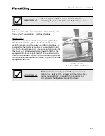
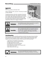
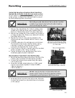
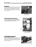

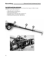

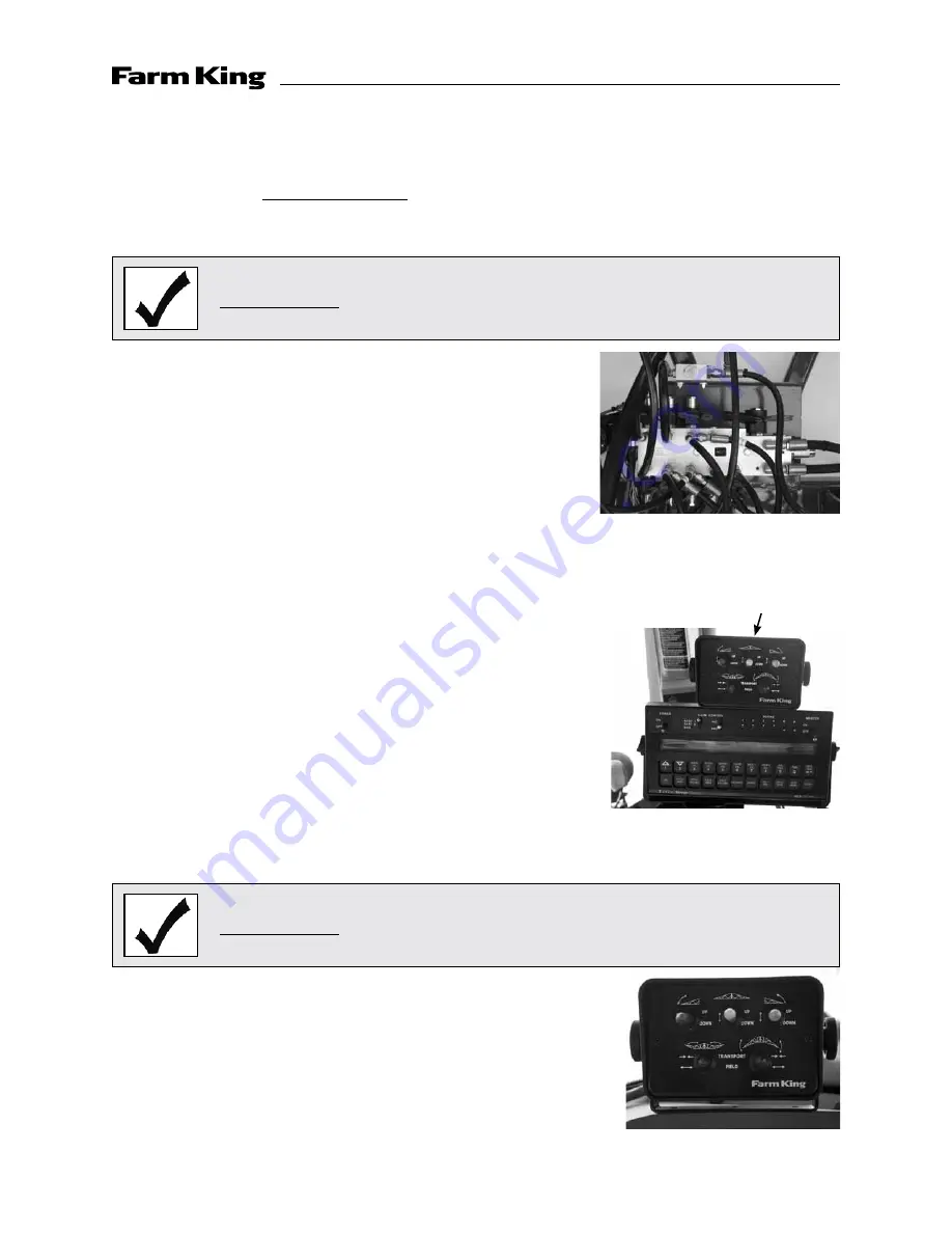
Vertical Fold Spray Boom Directional Stack Valve Block
Hydraulic Boom Function Controller (open center section)
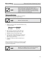
If your system is an open center system, or certain closed
center systems, configure the directional stack to account
for this by following these instructions:
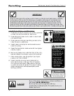
IMPORTANT
Not configuring the directional stack hydraulic manifold
correctly may cause tractor hydraulic system heating
and may damage the tractor.
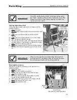
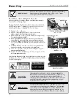
1. Remove the solenoid from the ”dump” cartridge valve
located on the left end of the valve manifold. Refer to
Section F, ”Parts & Schematics” for further information.
2. Remove the cartridge from the manifold. This location is
a storage location only. There are no hydraulic functions
associated with this port.
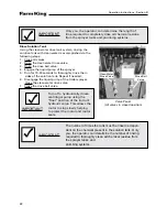
3. Replace the ”dump” valve port plug located on the
right end of the valve manifold with the ”dump” valve
cartridge.
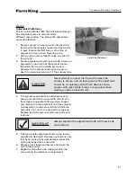
4. Install the solenoid on the cartridge valve and connect
the solenoid to the harness. See the harness wiring
schematic in Section F for information on which
connection lead operates the ”dump” valve.
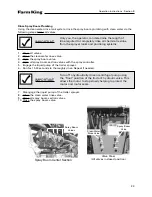
5. Place the plug in the port in the left side of the manifold
where you took out the ”dump” cartridge.
6. Torque all fittings to the specifications given on the
directional stack schematic in Section F.
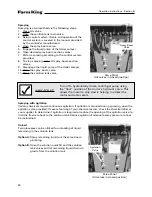
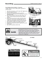
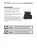
Directional Stack Valve Block Control Box Mounting:
1. Mount the directional stack control box to the top of the
solution spray controller with the brackets provided.
2. Connect the hydraulic hoses located near the sprayer
hitch to the tractor.
3. Route the controller power cables to a 12 VDC power
source in your tractor capable of at least 15 AMPs.
• Black is negative (-)
• Red is positive (+)
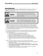
Hydraulic Control Directional Stack
Closed Center Hydraulic System Set
Up - Rear View
IMPORTANT
DO NOT remove the fuse or fuse holder from this
power source. These are for the protection of these
components and removal will void the warranty.
4. Route the harness out of the cab down to the hitch area.
Connect the harness from the control box to the harness
on the sprayer.
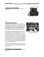
Raven Solution Spray Controller
Boom Control Box
Connection & Startup - Section C
Boom Control Switches
35
Summary of Contents for 1600
Page 1: ...Operator and Parts Manual 1600 High Clearance Sprayer 04 2010 SXL 26030 ...
Page 5: ...Safety Instruction Section A 5 ...
Page 11: ...Safety Decal Placement Safety Instructions Section A 11 ...
Page 12: ...Notes Safety Instructions Section A 12 ...
Page 13: ...Operation Instructions Section B 13 ...
Page 29: ...Connection Startup Section C 29 ...
Page 38: ...Connection Startup Section C Notes 38 ...
Page 39: ...Storage Section D 39 ...
Page 43: ...Maintenance Service Troubleshooting Section E 43 ...
Page 50: ...Maintenance Service Troubleshooting Section E Notes 50 ...
Page 51: ...Parts Schematics Section F 51 ...
Page 52: ...19 Description Decal Placement Parts Schematics Section F 52 ...
Page 54: ...Description Trailer Sprayer Light Kit Assembly Parts Schematics Section F 54 ...
Page 56: ...Description Frame Assembly Parts Schematics Section F 56 ...
Page 58: ...Description Drawbar Assembly Parts Schematics Section F 58 ...
Page 60: ...Description 10 Bolt Adjustable Axle Assembly Parts Schematics Section F 60 ...
Page 62: ...Description Cradle Assembly Parts Schematics Section F 62 ...
Page 64: ...Description Tank Spreader and Sight Gauge Parts Schematics Section F 64 ...
Page 66: ...Parts Schematics Section F Description Fold Over the Top Boom Center Section Assembly 66 ...
Page 68: ...Description Fold Boom Primary Section Assembly Parts Schematics Section F 68 ...
Page 70: ...Description Fold Boom Secondary Breakaway Assembly Parts Schematics Section F 70 ...
Page 72: ...Parts Schematics Section F Notes 72 ...
Page 74: ...Description Sprayer Hydraulic Routing Parts Schematics Section F 74 ...
Page 76: ...Description Fold Over The Top Boom Hydraulic Valve Breakdown Parts Schematics Section F 76 ...
Page 79: ...Parts Schematics Section F Notes 79 ...
Page 82: ...Description Spray Boom Cylinder Assembly Parts Schematics Section F 82 ...
Page 84: ...Description Boom Rephasing Cylinder Assembly Parts Schematics Section F 84 ...
Page 86: ...Description Pump Plumbing Parts Schematics Section F 86 ...
Page 88: ...Parts Schematics Section F Description Tank Plumbing 88 ...
Page 90: ...Description Raven Control Plumbing Parts Schematics Section F 90 ...
Page 93: ...Parts Schematics Section F Notes 93 ...
Page 94: ...Description Valve Mounting 94 Parts Schematics Section F ...
Page 96: ...Description Fold Over the Top Boom Plumbing Kit Parts Schematics Section F 96 ...
Page 98: ...Description Manual Fence Row Plumbing Parts Schematics Section F 98 ...
Page 100: ...Description Eductor Assembly Parts Schematics Section F 100 ...
Page 103: ...Warranty Section G 103 ...


