

Storage - Section D
42
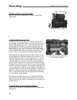
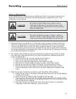
Sprayer Winterization (cont.)
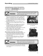
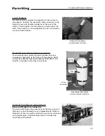
4. With the pump running, begin to winterize each of the segments in the plumbing system.
a. One at a time, slightly open the manual valves that feed the agitation and rinse system to
allow the solution to circulate through those segments of the plumbing. Allow the solution
to flow through the lines until the lines are full of the antifreeze solution. Close the valve
and repeat through the other segments of the pluming.
b. The next step is done with the controller set in the manual mode. If the system does not
work in the manual mode, enter a test speed into the console and operate as normal for
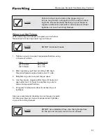
field operation. With a Raven system this is done by:
i. Touch the ”self test” button.
ii. Touch the ”enter” button.
iii. Touch the numbers ”5” and ”0”.
iv. Touch the ”enter” button. The console has now been told that the
sprayer is traveling at 5 mph.
v. Upon the completion of the winterization, the test speed can be
cancelled by repeating steps one and two, then enter ”0” in step three
instead of ”5” and ”0”.
c. One at a time, turn on each of the boom sections to allow the antifreeze solution to
be pumped through the controls and the boom valves. Run enough solution that the
antifreeze begins to spray out the boom sections.
d. Turn off the solution pump. Cycle the spray boom valves open and closed to allow the
antifreeze solution that is trapped in the hoses to drain back. Remove the strainers, clean
and reinstall.
5. If the sprayer is equipped with an eductor or foam marker, these must be winterized as well.
6. Verify that the antifreeze solution has been circulated through the whole system.
7. Disconnect the electrical connections. Apply a coating of dielectric grease to the terminals to
help prevent corrosion.
8. Inspect the complete machine for necessary repairs, grease all fittings and lubricate
moving parts.
Summary of Contents for 1600
Page 1: ...Operator and Parts Manual 1600 High Clearance Sprayer 04 2010 SXL 26030 ...
Page 5: ...Safety Instruction Section A 5 ...
Page 11: ...Safety Decal Placement Safety Instructions Section A 11 ...
Page 12: ...Notes Safety Instructions Section A 12 ...
Page 13: ...Operation Instructions Section B 13 ...
Page 29: ...Connection Startup Section C 29 ...
Page 38: ...Connection Startup Section C Notes 38 ...
Page 39: ...Storage Section D 39 ...
Page 43: ...Maintenance Service Troubleshooting Section E 43 ...
Page 50: ...Maintenance Service Troubleshooting Section E Notes 50 ...
Page 51: ...Parts Schematics Section F 51 ...
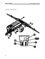
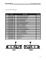
Page 52: ...19 Description Decal Placement Parts Schematics Section F 52 ...
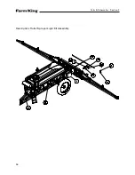
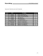
Page 54: ...Description Trailer Sprayer Light Kit Assembly Parts Schematics Section F 54 ...
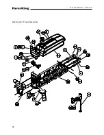
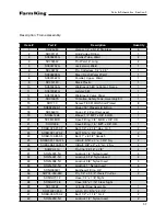
Page 56: ...Description Frame Assembly Parts Schematics Section F 56 ...
Page 58: ...Description Drawbar Assembly Parts Schematics Section F 58 ...
Page 60: ...Description 10 Bolt Adjustable Axle Assembly Parts Schematics Section F 60 ...
Page 62: ...Description Cradle Assembly Parts Schematics Section F 62 ...
Page 64: ...Description Tank Spreader and Sight Gauge Parts Schematics Section F 64 ...
Page 66: ...Parts Schematics Section F Description Fold Over the Top Boom Center Section Assembly 66 ...
Page 68: ...Description Fold Boom Primary Section Assembly Parts Schematics Section F 68 ...
Page 70: ...Description Fold Boom Secondary Breakaway Assembly Parts Schematics Section F 70 ...
Page 72: ...Parts Schematics Section F Notes 72 ...
Page 74: ...Description Sprayer Hydraulic Routing Parts Schematics Section F 74 ...
Page 76: ...Description Fold Over The Top Boom Hydraulic Valve Breakdown Parts Schematics Section F 76 ...
Page 79: ...Parts Schematics Section F Notes 79 ...
Page 82: ...Description Spray Boom Cylinder Assembly Parts Schematics Section F 82 ...
Page 84: ...Description Boom Rephasing Cylinder Assembly Parts Schematics Section F 84 ...
Page 86: ...Description Pump Plumbing Parts Schematics Section F 86 ...
Page 88: ...Parts Schematics Section F Description Tank Plumbing 88 ...
Page 90: ...Description Raven Control Plumbing Parts Schematics Section F 90 ...
Page 93: ...Parts Schematics Section F Notes 93 ...
Page 94: ...Description Valve Mounting 94 Parts Schematics Section F ...
Page 96: ...Description Fold Over the Top Boom Plumbing Kit Parts Schematics Section F 96 ...
Page 98: ...Description Manual Fence Row Plumbing Parts Schematics Section F 98 ...
Page 100: ...Description Eductor Assembly Parts Schematics Section F 100 ...
Page 103: ...Warranty Section G 103 ...


