Assembly - 500, 600, 660
25
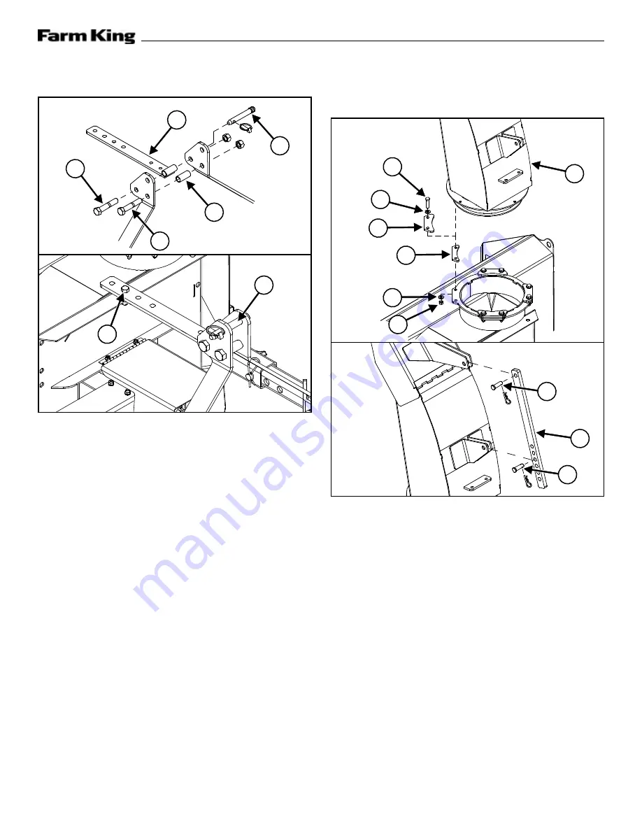
Figure 8
Attach the top brackets of the hitch arms by bolting
a 1” x 2-1/4” spacer (Item 1)
top brackets with a 3/4” x 4” bolt (Item 2)
and lock nut. Use the bottom front holes on the
brackets.
Attach the hitch top bar (Item 3)
between
the top brackets by bolting the welded tube on
the top bar between the top brackets with a 3/4”
x 4” bolt (Item 4)
and lock nut. Use the
bottom rear holes on the brackets.
Bolt the opposite end of the hitch top bar to the
top of the main frame with a 1/2” x 1-3/4” hex bolt
(Item 5)
and 1/2” lock nut. Use the same
hole position as the hitch tubes.
Tighten all hardware.
Attach a Category 1 top link pin (Item 6)
to the top holes of the top brackets.
The Category 1 pin is used for a standard three-
point hitch only. The bushing in the lower hole is
used for the Quick Hitch.
1
2
3
4
5
6
6
Discharge Spout
Figure 9
Align the discharge spout (Item 1)
main frame mount. Place the four spacers (Item
2)
around the spout ring on the mounts.
Lubricate the spout ring and spout clamps using
multipurpose lithium based grease.
Attach the spacers and clamps to the mounts using
eight 3/8” x 1-1/2” bolts (Item 4)
washers (Item 5)
, and eight lock nuts
(Item 6)
.
Align the spout deflector adjustment rod (Item 7)
on the mounts. Attach using two 1/2” x
1-1/2” clevis pins (Item 8)
and hair pins.
4
1
5
3
2
5
6
8
7
8
Summary of Contents for 500
Page 1: ...032016 FK311 OPERATOR AND PARTS MANUAL Snowblower Model 500 600 660 ...
Page 2: ......
Page 6: ...Warranty Registration Form 500 600 660 4 ...
Page 8: ...Introduction 500 600 660 6 ...
Page 12: ...Introduction 500 600 660 10 ...
Page 14: ...Safety 500 600 660 12 ...
Page 24: ...Assembly 500 600 660 22 ...
Page 30: ...Assembly 500 600 660 28 ...
Page 32: ...Operation 500 600 660 30 ...
Page 44: ...Operation 500 600 660 42 ...
Page 46: ...Maintenance 500 600 660 44 ...
Page 52: ...Maintenance 500 600 660 50 ...
Page 54: ...Parts Identification 500 600 660 52 ...
Page 66: ...Specifications And Shipping Kit Numbers 500 600 660 64 ...
Page 68: ...Specifications And Shipping Kit Numbers 500 600 660 66 HardwareTorque Values Metric Chart ...
Page 69: ...Specifications And Shipping Kit Numbers 500 600 660 67 Imperial Chart ...
Page 70: ...Specifications And Shipping Kit Numbers 500 600 660 68 ...
Page 72: ...Warranty 500 600 660 70 ...
Page 75: ......


