33
Assembly - High Speed Compact Disc
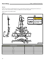
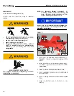
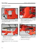
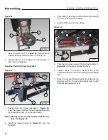
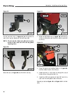
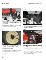
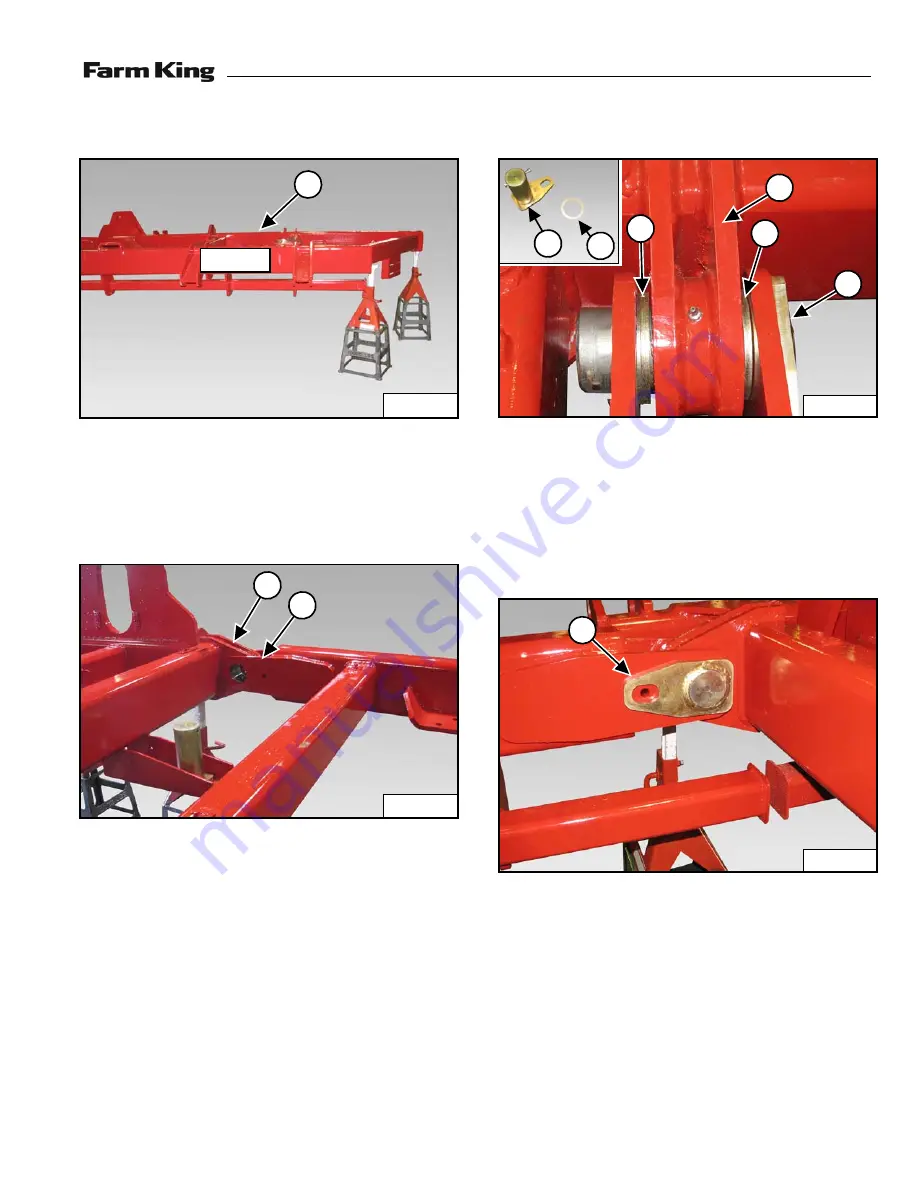
Figure 13
1.
Connect straps to LH wing frame (1,
an approved lifting device.
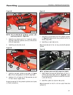
2.
Raise and move the LH wing frame to the left side of
the center frame.
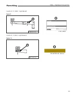
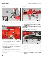
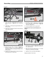
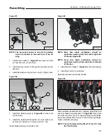
Figure 14
3.
Align the LH wing front and rear mounts (1,
)
with the center frame front and rear mounts (2) (rear
mount shown).
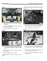
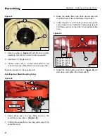
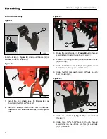
Figure 15
4.
) (as required) between
the center frame mount (2) and the LH wing mount
while inserting the mounting pin (3) on the front and
rear mounts.
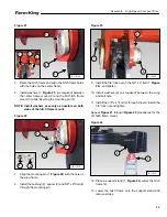
NOTE: Install washers as evenly as possible on both
sides of the center frame mount.
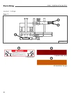
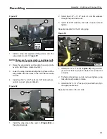
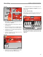
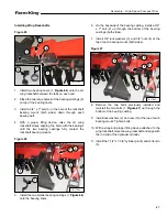
Figure 16
5.
Align the mounting pin (1,
the wing frame on the front and rear mounts.
B-17004
1
FRONT
B-17006
2
1
B-17001B
3
1
1
1
3
1
1
2
B-17003
1
Summary of Contents for HS8525
Page 2: ......
Page 4: ...4 Table of Contents High Speed Compact Disc ...
Page 6: ...Warranty Registration High Speed Compact Disc 6 ...
Page 10: ...10 Introduction High Speed Compact Disc ...
Page 14: ...14 Safety High Speed Compact Disc ...
Page 28: ...28 Safety High Speed Compact Disc ...
Page 30: ...30 Assembly High Speed Compact Disc ...
Page 74: ...74 Assembly High Speed Compact Disc ...
Page 76: ...76 Operation High Speed Compact Disc ...
Page 92: ...92 Maintenance High Speed Compact Disc ...
Page 102: ...102 Part Identification High Speed Compact Disc ...
Page 104: ...104 Part Identification High Speed Compact Disc WHEELS TIRES WINGS 3 1 4 5 2 88717299 ...
Page 152: ...152 Part Identification High Speed Compact Disc BLADES 2 1 3 88717644 ...
Page 154: ...154 Part Identification High Speed Compact Disc ...
Page 156: ...156 Specifications High Speed Compact Disc ...
Page 166: ...166 Specifications High Speed Compact Disc ...
Page 167: ...167 Warranty High Speed Compact Disc WARRANTY WARRANTY 169 ...
Page 168: ...168 Warranty High Speed Compact Disc ...
Page 171: ......

