51
Assembly - High Speed Compact Disc
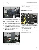
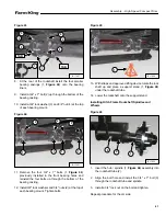
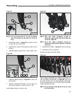
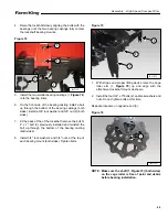
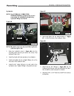
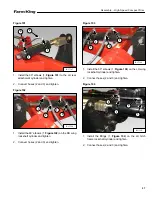
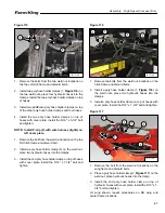
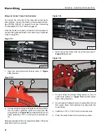
Figure 79
5.
Tighten the four bolts (1,
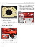
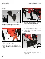
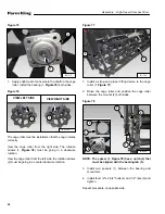
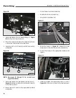
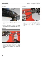
Figure 80
6.
Slide the cage roller (1,
one side.
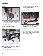
7.
Check the gap (2) between the bearing and the cage
roller. Check how many washers (3) fit in the gap.
Example: Eight washers fit in the gap, four washers will
be installed on each side.
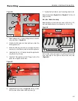
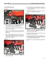
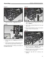
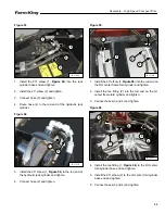
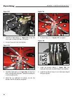
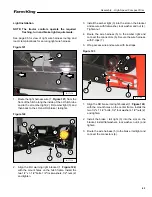
Figure 81
8.
Install a strap and proper lifting device to the cage
roller (1,
9.
Install a strap and proper lifting device to the cage
roller arm (2).
10. Remove the four bolts 3/4" x 3" bolts (3), nuts and lock
washers. Remove the cage roller arm.
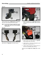
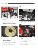
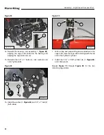
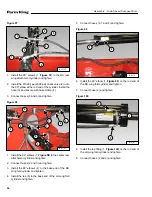
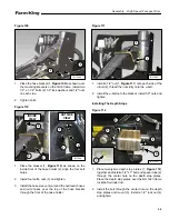
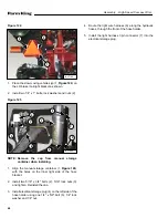
Figure 82
) out from the
bearing / arm assembly on the opposite side.
12. Install the correct amount of washers (2) onto the
shaft (both sides of the cage roller).
13. Reinstall the cage roller into the bearing / arm
assembly.
B-17114
1
B-17080
1
3
2
1
2
3
2
B-17114
B-17114
1
2
Summary of Contents for HS8525
Page 2: ......
Page 4: ...4 Table of Contents High Speed Compact Disc ...
Page 6: ...Warranty Registration High Speed Compact Disc 6 ...
Page 10: ...10 Introduction High Speed Compact Disc ...
Page 14: ...14 Safety High Speed Compact Disc ...
Page 28: ...28 Safety High Speed Compact Disc ...
Page 30: ...30 Assembly High Speed Compact Disc ...
Page 74: ...74 Assembly High Speed Compact Disc ...
Page 76: ...76 Operation High Speed Compact Disc ...
Page 92: ...92 Maintenance High Speed Compact Disc ...
Page 102: ...102 Part Identification High Speed Compact Disc ...
Page 104: ...104 Part Identification High Speed Compact Disc WHEELS TIRES WINGS 3 1 4 5 2 88717299 ...
Page 152: ...152 Part Identification High Speed Compact Disc BLADES 2 1 3 88717644 ...
Page 154: ...154 Part Identification High Speed Compact Disc ...
Page 156: ...156 Specifications High Speed Compact Disc ...
Page 166: ...166 Specifications High Speed Compact Disc ...
Page 167: ...167 Warranty High Speed Compact Disc WARRANTY WARRANTY 169 ...
Page 168: ...168 Warranty High Speed Compact Disc ...
Page 171: ......

