Operation - RT17, RT19 Tedder
27
PTO Driveline Length Check
Due to variations in distances between tractor PTO
shafts and implement input shafts, drivelines may
need to be shortened or a longer shaft may be
required.
When fitting the implement to the tractor, the
PTO driveline, with telescoping sections, must
be inspected. When the sections are at the most
compressed operating position, the sections must
not “bottom out”.
At its shortest length, there must be at least 2 in.
(50.8 mm) of clearance between each section end
and opposite section end at the most compressed
operating position.
When the sections are at the most extended
position, there must be sufficient engagement
between the sections.
At its farthest operating extension, a minimum
section engagement of 33% of shaft length must
be maintained.
WARNING
AVOID INJURY OR DEATH
•
Do NOT exceed the rated implement PTO speed.
•
Stay clear of rotating driveline.
•
Keep bystanders away.
•
Keep hands, feet, clothing and long hair away.
•
Keep PTO shields and all guards in place.
•
Disengage PTO, move the tractor controls to
the Neutral position, stop the engine and make
sure all rotating components are stopped before
leaving the operator’s position.
•
Do NOT service the tractor or implement with
the PTO engaged.
•
Do NOT service the implement in a raised
position unless properly blocked and with all
rotating components stopped.
•
Disengage PTO for road travel.
PTO Driveline Bottoming Out Check
Stop the engine and leave the operator’s position
(See “Leaving The Operator’s Position” in
Operation section).
Make sure the PTO driveline and all rotating
components have come to a complete stop before
leaving the operator’s position (if applicable).
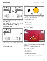
Figure 7
1. Disconnect the PTO driveline from the tractor and
slide the PTO driveline together until fully retracted
(compressed).
2. Measure the retracted (compressed) length of PTO
driveline
[Figure 7]
.
3. Extend the PTO driveline 2 in. (50.8 mm) from the
retracted length and place a mark on the inner guard
at the end of the outer guard
[Figure 7].
4. Reattach the PTO driveline to the tractor PTO shaft.
5. Enter the operator’s position. Start the engine.
6. With the rear PTO DISENGAGED, raise and lower
the implement and watch the PTO driveline extend
and retract.
7. If the outer PTO driveline guard slides in (retracts)
over the mark at any point of travel, the PTO driveline
needs to be shortened.
MARK INNER
GUARD HERE
RETRACTED
(COMPRESSED LENGTH)
2” (50.8 mm)
Summary of Contents for RT17
Page 1: ...092018 R0002 OPERATOR AND PARTS MANUAL Tedder Model RT17 RT19 ...
Page 2: ......
Page 6: ...Warranty Registration Form RT17 RT19Tedder 4 ...
Page 8: ...Introduction RT17 RT19Tedder 6 ...
Page 12: ...Introduction RT17 RT19Tedder 10 ...
Page 14: ...Safety RT17 RT19Tedder 12 ...
Page 20: ...Safety RT17 RT19Tedder 18 Equipment and Safety Decals GREASE POINT ...
Page 22: ...Safety RT17 RT19Tedder 20 ...
Page 24: ...Operation RT17 RT19Tedder 22 ...
Page 40: ...Maintenance RT17 RT19Tedder 38 ...
Page 46: ...Maintenance RT17 RT19Tedder 44 ...
Page 48: ...Parts Identification RT17 RT19Tedder 46 ...
Page 58: ...Parts Identification RT17 RT19Tedder 56 Pull Type Mechanical Angle Adjust Release Rope ...
Page 60: ...Parts Identification RT17 RT19Tedder 58 Pull Type Hydraulic Angle Adjust ...
Page 62: ...Parts Identification RT17 RT19Tedder 60 Mounted Type Guards ...
Page 64: ...Parts Identification RT17 RT19Tedder 62 Mounted Type Hitch PTO Release Rope ...
Page 66: ...Parts Identification RT17 RT19Tedder 64 Mounted Type Hydraulic Hoses Stabilizer Bars ...
Page 72: ...Parts Identification RT17 RT19Tedder 70 ...
Page 74: ...Specifications And Shipping Kit Numbers RT17 RT19Tedder 72 ...
Page 78: ...Specifications And Shipping Kit Numbers RT17 RT19Tedder 76 ...
Page 80: ...Warranty RT17 RT19Tedder 78 ...
Page 83: ......


