background image

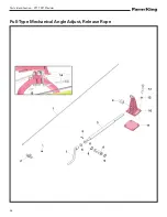
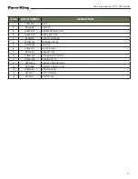
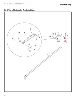
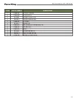
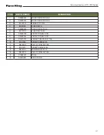
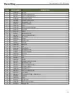
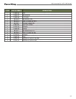
Parts Identification - RT17, RT19 Tedder

63

ITEM

PART NUMBER

DESCRIPTION

1

R18033546

FRAME

2

R3010405

SCREW TE M16X120 ZN

3

R3020204

SELF LOCKING NUT M16

4

R18033973

SUPPORT ROPE 3P

5

R3011268

SCREW TE M12L20 ZN

6

R3030162

WASHER M12 ZN

7

R3080105

ELASTIC PIN 8X50

8

R18032266

BUSH

9

R12240237

BUSH GLYCODUR 3030426

10

R18032257

SUPPORT

11

R12071212

BUSH

12

R3030176

WASHER M22 ZN

13

R3020222

SELF LOCKING NUT M22

14

R18032254

3P ATTACK

15

R18032260

STAND

16

R3040117

ELASTIC PIN

17

R3080204

PIN Ø10

18

R18033185

BRACKET

19

R12310122

PIN

20

R18032362

PIN Ø22 L.91

21

R3030176

WASHER M22 ZN

22

R3080109

ELASTIC PIN 6X30

23

R18033216

COLLAR

24

R12310307

PIN 2°

25

R3080202

PIN

26

R18032512

HOOK

27

R3011707

SCREW TE M12L45 10.9 ZN

28

R3030162

WASHER M12 ZN

29

R3020202

SELF LOCKING NUT M12

30

R3011210

SCREW TE  M8X50

31

R18032256

PIN Ø28 L.135

32

R3020209

SELF LOCKING NUT M8

33

R12310115

PIN 3POINT

34

R8020438

PTO SHAFT 900 NM  L.1480 GVL GV

35

R9060108

HANDLE

36

R18033715

ROPE

37

R3070118

U BOLT M10

38

R12881497

BASE COLLAR 30X20

39

R3120128

SEEGER Ø16

Summary of Contents for RT17

Page 1: ...092018 R0002 OPERATOR AND PARTS MANUAL Tedder Model RT17 RT19 ...

Page 2: ......

Page 3: ...onfiguration 31 Field Operation 32 Adjustments 34 Transport Configuration 35 Maintenance 37 Service Schedule Chart 39 Lubrication 40 Tine Replacement 42 Safety Sign Decal Installation 42 Storage And ReturnTo Service 43 Parts Identification 45 Center Frame 47 Wing Frame 50 Wing Lift Locking Device Guards 52 Manufacturer s Statement For technical reasons Buhler Industries Inc reserves the right to m...

Page 4: ...e Guards 60 Mounted Type Hitch PTO Release Rope 62 Mounted Type Hydraulic Hoses Stabilizer Bars 64 Hydraulic Cylinder Angle Adjust 66 Hydraulic Cylinder Wing Fold 67 PTO Shaft RT17 68 PTO Shaft RT19 69 Specifications And Shipping Kit Numbers 71 Specifications 73 Shipping Kit And Bundle Numbers 73 HardwareTorque Values 74 Warranty 77 Farm King Base Limited Warranty 79 ...

Page 5: ...Raise and lower wings Adjust angle of rotary group Lubricate machine Check wheel bolt torque All fasteners tight Check tire pressure Check hydraulic hoses Safety chain is on hitch All decals installed Guards and shields installed and secure Review operating and safety instructions Date Dealer Rep Signature The above equipment and Operator And Parts Manual have been received by me and I have been t...

Page 6: ...Warranty Registration Form RT17 RT19Tedder 4 ...

Page 7: ...Farm King equipment READ AND UNDERSTAND THIS OPERATOR AND PARTS MANUAL BEFORE OPERATING YOUR FARM KING EQUIPMENT If you have any questions see your Farm King dealer This manual may illustrate options and accessories not installed on your Farm King equipment Owner s Information 7 Serial Number Location 7 Equipment Identification 8 Component Location PullType 8 Component Location MountedType 9 ...

Page 8: ...Introduction RT17 RT19Tedder 6 ...

Page 9: ...he accuracy of this publication Farm King makes no warranty or guarantee of any kind written or expressed implied or otherwise with regard to the information contained within this manual Farm King assumes no responsibility for any errors that may appear in this manual and shall not be liable under any circumstances for incidental consequential or punitive damages in connection with or arising from...

Page 10: ...troduction RT17 RT19Tedder 8 Equipment Identification Component Location PullType SUPPORT JACK TOWING CONNECTION SIDE PROTECTION GUARD SIDE PROTECTION GUARD PTO GEAR BOX ROTARY UNIT WING LOCK TINES WHEELS ...

Page 11: ...duction RT17 RT19Tedder 9 Component Location MountedType THREE POINT CONNECTIONS SUPPORT JACK SIDE PROTECTION GUARD REAR PROTECTION GUARD SIDE PROTECTION GUARD PTO GEAR BOX ROTARY UNIT WING LOCK TINES WHEELS ...

Page 12: ...Introduction RT17 RT19Tedder 10 ...

Page 13: ...or 13 Use Safety Rules 14 Safety Rules For PowerTake Off PTO Driven Equipment 14 Machine Requirements And Capabilities 15 Transport Safety 15 Fire Prevention 16 Maintenance 16 Operation 16 Starting 16 Electrical 16 Hydraulic System 16 Fueling 16 Welding And Grinding 17 Fire Extinguishers 17 Equipment and Safety Decals 18 Safety Sign Off Form 19 ...

Page 14: ...Safety RT17 RT19Tedder 12 ...

Page 15: ...or who is taking prescription drugs must get medical advice to determine if he or she can safely operate a machine and the equipment Understand the written instructions rules and regulations The written instructions from Farm King include the Warranty Registration Dealer Inspection Report Operator And Parts Manual and machine signs decals Check the rules and regulations at your location The rules ...

Page 16: ...unction and or safety and could affect the life of the equipment Stop tractor engine place all controls in neutral set park brake remove ignition key and wait for all moving parts to stop before servicing adjusting repairing unplugging or filling DO NOT make any adjustments or repairs on the equipment while the machine is running Keep shields and guards in place Replace if damaged Keep hands feet ...

Page 17: ...l blocks underneath and support the equipment securely before working under raised equipment Keep bystanders clear of moving parts and the work area Keep children away Use increased caution on slopes and near banks and ditches to prevent overturn Make certain that the Slow Moving Vehicle SMV emblem is installed so that it is visible and legible When transporting the equipment use the flashing warn...

Page 18: ...ce section Do not use the machine where exhaust arcs sparks or hot components can contact flammable material explosive dust or gases Starting Do not use ether or starting fluids on any engine that has glow plugs These starting aids can cause explosion and injure you or bystanders Use the procedure in the tractor s operator s manual for connecting the battery and for jump starting Electrical Check ...

Page 19: ...ing or welding painted parts Wear dust mask when grinding painted parts Toxic dust or gas can be produced Dust generated from repairing nonmetallic parts such as hoods fenders or covers can be flammable or explosive Repair such components in a well ventilated area away from open flames or sparks Fire Extinguishers Know where fire extinguishers and first aid kits are located and how to use them Ins...

Page 20: ...Safety RT17 RT19Tedder 18 Equipment and Safety Decals GREASE POINT ...

Page 21: ...and the Occupational Safety and Health Administration OSHA Anyone who will be operating and or maintaining the Rotary Rake must read and clearly understand ALL Safety Operating and Maintenance information presented in this manual Annually review this information before the season start up and make these periodic reviews of SAFETY and OPERATION a standard practice for all of your equipment An untra...

Page 22: ...Safety RT17 RT19Tedder 20 ...

Page 23: ...ractor 24 Three Point Hitch 24 PullType Hitch 25 Connecting PTO Driveline 26 PTO Driveline Length Check 27 PTO Driveline Bottoming Out Check 27 ReducingThe PTO Driveline Length 28 PTO Driveline Engagement Check 29 Connecting Hydraulic Hoses 30 Work Configuration 31 Field Operation 32 Adjustments 34 Three Point Hitch Models 34 Pull Type Models 34 Transport Configuration 35 ...

Page 24: ...Operation RT17 RT19Tedder 22 ...

Page 25: ...ll electrical connections are tight 7 Check the tines Remove any twine wire or other material that has become entangled 8 Check the wheel bolt torque EnteringThe Operator s Position Enter the operator s position start the engine and release the parking brake IMPORTANT Follow the instructions in your tractor s operation manual for the correct procedure LeavingThe Operator s Position Always perform ...

Page 26: ...or to the equipment left and right lower mounting pins Reinstall the retaining pins Note Always use retaining pins with a locking device Lower the top link of the three point hitch until it aligns with the implement upper mount Reinstall the mounting pin and retaining pin Note It may be necessary to lengthen or shorten the top link to align it with the implement mounting hole See the tractor s ope...

Page 27: ...ractor and the equipment when backing up to the equipment for connecting Keep fingers and hands out of pinch points when connecting and disconnecting equipment Figure 4 Move the tractor backwards aligning the drawbar with the equipment hitch Item 1 Lower or raise the support jack Item 2 to properly align the drawbar and hitch Figure 4 Move the tractor backwards aligning pin holes with the equipmen...

Page 28: ...ee point hitch Make sure the PTO driveline is of adequate length and that u joints are in the correct phase Remove the PTO driveline from the storage position if applicable Figure 6 Retract the collar Item 1 Figure 6 and slide the PTO driveline onto the tractor PTO shaft Release the collar and the driveline will lock onto the shaft Push and pull the PTO driveline back and forth several times and m...

Page 29: ... all rotating components are stopped before leaving the operator s position Do NOT service the tractor or implement with the PTO engaged Do NOT service the implement in a raised position unless properly blocked and with all rotating components stopped Disengage PTO for road travel PTO Driveline Bottoming Out Check Stop the engine and leave the operator s position See Leaving The Operator s Positio...

Page 30: ...Enter the operator s position See Entering The Operator s Position in the Operation section Start the engine Raise or lower the three point implement to get the shortest distance between the tractor PTO shaft and three point implement gearbox PTO shaft Stop the engine and leave the operator s position Pull the PTO driveline apart and reinstall each individual section one half to the tractor PTO sh...

Page 31: ...eline length by 1 667 to determine the PTO driveline Maximum Operating Length i e 25 5 in 647 7 mm x 1 667 42 5 in 1079 7 mm Maximum Operating Length 4 Attach the PTO driveline to the tractor PTO output shaft 5 Enter the operator s position See Entering The Operator s Position in the Operation section 6 With the PTO driveline attached position the three point implement to where the telescoping PTO...

Page 32: ...of hands Keep all components in good repair Connecting Hydraulic Hoses Tedders are equipped with a hydraulic wing lift system Figure 11 Push the male couplers into female couplers on the tractor until they are fully engaged and locked Figure 11 Note Make sure the quick couplers are fully engaged If the quick couplers do not fully engage check to see that the couplers are the same size and type IMP...

Page 33: ...ly pull the two strings to unlock the rams from their mechanical locking devices Item 1 on each wing Figure 12 WARNING AVOID INJURY OR DEATH Before unlocking the wings look in all directions and make sure no bystanders especially small children are in the work area Figure 13 The wings will descend once unlocked Three Point Models Lower the hydraulic lifter until the equipment front tines skim the ...

Page 34: ...a maximum speed of 9 mph 14 kph CAUTION Read operator and parts manual before operating the implement Do not permit riders Keep all guards and shields in place Keep hands feet clothing and hair away from moving parts Stop engine set brake remove key and wait for all moving parts to stop before servicing adjusting repairing and unplugging Remove bystanders especially children before starting or whi...

Page 35: ...otary group rotation is as shown Figure 16 WARNING AVOID INJURY OR DEATH During operation make sure no bystanders especially small children are in the work area Keep away from all dangerous areas around the machine DANGER DANGER DANGER DANGER ...

Page 36: ...e Place all controls in neutral engage the park brake stop the engine and wait for all moving parts to stop Leave the operator s position Three Point Hitch Models Figure 17 Turn the lever Item 1 counterclockwise Direction A to reduce the angle of the rotary groups Figure 17 Turn the lever Item 1 clockwise Direction B to increase the angle of the rotary groups Figure 17 Pull Type Models Figure 18 T...

Page 37: ... for road travel Keep PTO shields and all guards in place Keep bystanders away Do not allow riders IMPORTANT Never exceed 20 mph 32 kph during road travel WARNING Use of an unapproved hitch or tractor tow vehicle can result in loss of control leading to serious injury or death Tractor tow vehicle and hitch must have the rated capacity to tow equipment Figure 19 Act on the hydraulic controls and ra...

Page 38: ...dder 36 Figure 21 Mounted Type Models Raise the three point hitch and lift the equipment off the ground The lowest point of the equipment must be 15 to 20 in 40 to 50 cm off the ground Figure 21 10 20 IN MOUNTED TYPE MODEL ...

Page 39: ...7 RT19Tedder 37 Maintenance Service Schedule Chart 39 Lubrication 40 Recommendations 40 Locations 40 Tine Replacement 42 Safety Sign Decal Installation 42 Storage And ReturnTo Service 43 Storage 43 ReturnTo Service 43 ...

Page 40: ...Maintenance RT17 RT19Tedder 38 ...

Page 41: ...ead through this troubleshooting section please call your local distributor dealer or factory Before you call please have this Operator And Parts Manual and the serial number of your machine at hand Maintenance work must be done at regular intervals Failure to do so will result in excessive wear and early failures The service schedule is a guide for correct maintenance of the equipment DESCRIPTION...

Page 42: ...operly grounded Use adequate light for the job Use only tools jacks and hoists of sufficient capacity for the job Replace and secure all shields removed during servicing before operating Use heavy leather gloves to handle sharp objects Check hydraulics regularly for leaks Use cardboard to look for leaks and use hand and eye protection Relieve pressure on hydraulic system before repairing or adjust...

Page 43: ...ease every 50 hours 1 1 2 2 8 10 1 2 1 2 2 Figure 25 Lubrication point locations Item 1 are identified with a sticker Item 2 Figure 25 Lubrication points include Wheels Driveline mounts Hitch pivot points Wing pivot points Grease every 50 hours Figure 26 Check the grease in the transfer box Item 1 Internal components must be immersed in grease Figure 26 Use grease type AGIP GREASE MU EP2 Grease ty...

Page 44: ...the safety sign decal Press on the safety sign decal where the backing paper has been removed Slowly remove the remaining backing paper pressing on the safety sign decal as the backing paper is removed Using the backing paper pressing firmly move the backing paper over the entire safety sign decal area Note Small air pockets can be pierced with a pin and smoothed out using the piece of the backing...

Page 45: ... hitch and all welds on the equipment for wear and damage Check for loose hardware missing guards tines or damaged parts Check for damaged or missing safety signs decals Replace if necessary Replace worn or damaged parts Touch up all paint nicks and scratches to prevent rusting Place the equipment in a dry protected shelter Note If a dry protected shelter is not available cover with a waterproof t...

Page 46: ...Maintenance RT17 RT19Tedder 44 ...

Page 47: ...est to exactly identify the required part Center Frame 47 Wing Frame 50 Wing Lift Locking Device Guards 52 Pull Type Hydraulic Hoses 54 Pull Type Hitch PTO 55 Pull Type Mechanical Angle Adjust Release Rope 56 Pull Type Hydraulic Angle Adjust 58 Mounted Type Guards 60 Mounted Type Hitch PTO Release Rope 62 Mounted Type Hydraulic Hoses Stabilizer Bars 64 Hydraulic Cylinder Angle Adjust 66 Hydraulic ...

Page 48: ...Parts Identification RT17 RT19Tedder 46 ...

Page 49: ...8 R LATERAL ARM RT19 3 R18033727 L LATERAL ARM RT17 R18033729 L LATERAL ARM RT19 4 R3010814 HH SCREW M14X190 ZN 5 R3020203 SELF LOCKING NUT M10 6 R4010816 PLUG 3 4 7 R3030409 COPPER WASHER 8 R8010302 BEVEL PINION CENTRAL BOX 9 R12240190 BEARING 6009 2RS 10 R18033775 SLEEVE 11 R12320301 SHAFT PDF 12 R12240145 BEARING 6207 2RS 13 R3120105 SNAP RING E 72 ...

Page 50: ...X30 ZN 31 R3020209 SELF LOCKING NUT M8 32 R18033544 PLATE 33 R18033777 SHAFTTRANSMISSION L 1560 MM RT17 R12010211 SHAFTTRANSMISSION L 1783 MM RT19 34 R3110002 TAB 8X7X35 35 R3110008 TAB 8X7X30 36 R18034226 CENTRAL PIN WITH BRACKET 37 R3010605 SCREWTCEI M12X55 38 R12240109 BEARING 6207 39 R18031169 or R8010317 BEVEL CROWN FOR ROTOR 40 R18031171 or R2010422 SAFETY LOOP 41 R12240160 BEARING 32007A 42...

Page 51: ...20202 SELF LOCKING NUT M12 58 R18033631 R COMPLETE ARM RT17 R18033736 R COMPLETE ARM RT19 59 R3120126 AXIAL WASHER PS 355205 60 R12260003 SEAL 61 R4010702 BAND 62 R9070101 COVER 63 R18033216 COLLAR C3 64 R3010813 HH SCREW M14X170 ZN 65 R18033702 SUPPORT SHAFT 66 R12240108 BEARING 6206 2RS 67 R3120108 SNAP RING I 62 68 R18033740 R COMPLETE ARM RT17 R18033734 R COMPLETE ARM RT19 ...

Page 52: ...17 RT19Tedder 50 Wing Frame ITEM PART NUMBER DESCRIPTION 1 R18033535 CROSS ATTACK L 1365 MM RT17 R18033730 CROSS ATTACK L 1590 MM RT19 2 R18033216 COLLAR C3 3 R3010231 SCREWTE M12X70 4 R3030800 WASHER M12 S E 5 R4010702 BAND ...

Page 53: ...RT SHAFT 19 R12240108 BEARING 6206 2RS 20 R18033486 LATERAL ARM RT17 R18033731 LATERAL ARM RT19 21 R18032307 AXLE FENDER SX 22 R12070314 INTERNAL SHIELD 23 R12240128 BEARING 6205 2RS 24 R12170106 WHEEL 16 650 8 COMPLETE R12070327 TIRE 16 650 8 R12070326 AIRTUBE 16 650 8 R12070325 WHEEL RIM 25 R12070307 SPACER 26 R12070315 EXTERNAL SHIELD 27 R3030175 WASHER M16 ZN 28 R3020204 SELF LOCKING NUT M16 2...

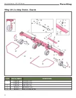
Page 54: ...tion RT17 RT19Tedder 52 Wing Lift Locking Device Guards ITEM PART NUMBER DESCRIPTION 1 R18033536 CYLINDER RT17 R18033732 CYLINDER RT19 2 R12881406 END POINT D 50 3 R3030156 WASHER M16 ZN 4 R3020209 SELF LOCKING NUT M8 ...

Page 55: ...OLLER 20 R3120128 RING SEEGER D 16 21 R3020202 SELF LOCKING NUT M12 22 R3090102 GREASE ZERK M6X1 23 R18032318 or R14013144 RIGHT WHEEL AXLE 24 R12070314 INTERNAL SHIELD 25 R12240113 BEARING 6205 2RS 26 R12070307 SPACER 27 R12170106 WHEEL COMPLETE 16 650 8 28 R12070315 EXTERNAL SHIELD 29 R3030175 WASHER M16 ZN 30 R3020204 SELF LOCKING NUT M16 31 R18032316 LEFT WHEEL AXLE 32 R3030800 WASHER S E M12 ...

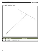
Page 56: ...Parts Identification RT17 RT19Tedder 54 Pull Type Hydraulic Hoses ITEM PART NUMBER DESCRIPTION 1 R12760724 HYDRAULIC HOSE L 1350 2 R12760722 HYDRAULIC HOSE L 3300 ...

Page 57: ...3 R9190018 RUBBER CUP Ø32 4 R18032774 STAND 5 R18033195 PIN 6 R3040202 ELASTIC PIN 5X100 7 R18033636 PIN 8 R3030168 WASHER M20 ZN 9 R3020216 SELF LOCKING NUT M20 10 R18033342 COLLAR CF2 11 R18033216 COLLAR C3 12 R3070118 U BOLT M10 13 R8020438 PTO SHAFT 90 KG M L 1480 RT17 R8020426 PTO SHAFT 120 KG M L 1520 RT19 14 R12881497 BASE COLLAR 30X20 ...

Page 58: ...Parts Identification RT17 RT19Tedder 56 Pull Type Mechanical Angle Adjust Release Rope ...

Page 59: ...R18033714 SNAIL M24 L 55 5 R3080102 ELASTIC PIN 6X36 6 R12280003 WASHER AS2035 7 R18030697 HANDLE 8 R18033711 FRONT SNAIL 9 R3120146 SEEGER D 35 10 R18034347 ATTACK REGULATION 11 R18035418 PLATE ATTACK 12 R3030322 GROWER WASHER M16 13 R3010408 SCREWTE M16X110 ZN 14 R18030691 HANDLE STOP 15 R3040201 SPLIT PIN 3X60 16 R3160101 CRICKET Ø8 ...

Page 60: ...Parts Identification RT17 RT19Tedder 58 Pull Type Hydraulic Angle Adjust ...

Page 61: ...035418 PLATE ATTACK 3 R3010408 SCREWTE M16X110 ZN 4 R3030322 GROWER WASHER M16 5 R18033957 CYLINDER 6 R3120157 SEEGER E20 7 R18033713 PIN HYDRAULIC CYLINDER D20 L100 8 R18033321 PIN Ø25 L 160 9 R18033716 BUSH 10 R3010760 SCREWTEM6X55 ZN 11 R3020213 SELF LOCKING NUT M6 12 R12760723 HYDRAULIC HOSE L 3400 ...

Page 62: ...Parts Identification RT17 RT19Tedder 60 Mounted Type Guards ...

Page 63: ...070118 U BOLTO M10 5 R18033552 UNION PROTECTION 6 R3170120 U BOLTO M10X40 7 R18033708 PROTECTION BACK DX 8 R18033555 PROTECTION BACK SX 9 R14013219 CONNECTION PROTECTION 10 R3011258 SCREWTE M8X45 ZN 11 R3020209 SELF LOCKING NUT M8 12 R3011672 SCREWTE M16X16 ZN 13 R3030160 WASHER M6 EXL ZN 14 R3020213 SELF LOCKING NUT M6 15 R12880422 PANEL 16 R14080901 BASE COLLAR ...

Page 64: ...Parts Identification RT17 RT19Tedder 62 Mounted Type Hitch PTO Release Rope ...

Page 65: ...P ATTACK 15 R18032260 STAND 16 R3040117 ELASTIC PIN 17 R3080204 PIN Ø10 18 R18033185 BRACKET 19 R12310122 PIN 20 R18032362 PIN Ø22 L 91 21 R3030176 WASHER M22 ZN 22 R3080109 ELASTIC PIN 6X30 23 R18033216 COLLAR 24 R12310307 PIN 2 25 R3080202 PIN 26 R18032512 HOOK 27 R3011707 SCREWTE M12L45 10 9 ZN 28 R3030162 WASHER M12 ZN 29 R3020202 SELF LOCKING NUT M12 30 R3011210 SCREWTE M8X50 31 R18032256 PIN...

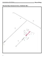
Page 66: ...Parts Identification RT17 RT19Tedder 64 Mounted Type Hydraulic Hoses Stabilizer Bars ...

Page 67: ...INDER 4 R3030168 WASHER M20 ZN 5 R3020216 SELF LOCKING NUT M20 6 R3011312 SCREWTE M8X90 ZN 7 R18033165 SUPPORT SPRING 8 R11010708 SPRING 9 R18033569 BRAKE 10 R3030157 WASHER M8 EXL ZN 11 R3020209 SELF LOCKING NUT M8 12 R11010536 SPRING 13 R18033549 ROD 14 R12760724 HYDRAULIC HOSE L 1350 MM 15 R12760725 HYDRAULIC HOSE L 2400 ...

Page 68: ...TEM PART NUMBER DESCRIPTION 1 R18053185 SUPPORT 2 R18053179 HANDLE 3 R18053180 BUSH 4 R3080103 ELASTIC PIN 6X40 5 R18053181 ROD 6 R18053182 HEAD 7 R18033666 SEAL KIT COMP 8 R3020232 SELF LOCKING NUT M20 9 R18053184 CYLINDER WITH VALVE 10 R18033957 CYLINDER COMPLETE Ø50 C 100 ...

Page 69: ...ing Fold ITEM PART NUMBER DESCRIPTION 1 R18053172 ROD RT17 R18053174 ROD RT19 2 R18053175 HEAD 3 R18033665 SEAL KIT RT17 R18033667 SEAL KIT RT19 4 R18053177 CYLINDER RT17 R18053178 CYLINDER RT19 5 R18033536 CYLINDER COMPLETE RT17 R18033732 CYLINDER COMPLETE RT19 ...

Page 70: ... FORK 2 R12881457 CROSS 3 R12881458 FORK SPLINED 4 R12881459 TUBE EXT L 1085 5 R12881460 TUBE INT L 1085 6 R12881461 FORK INT 7 R12881462 LIMITING 8 R12881463 ELASTIC PIN 8X55 DIN 1481 9 R12881464 EXTERNAL PROTECTION L 1210 10 R12881465 INTERNAL PROTECTION L 1210 R8020438 PTO SHAFT COMPLETE RT17 ...

Page 71: ... FORK 2 R12881467 CROSS 3 R12881468 FORK SPLINED 4 R12881469 TUBE EXT L 1060 5 R12881470 TUBE INT L 1060 6 R12881471 FORK INT 7 R12881472 LIMITING 8 R12881473 ELASTIC PIN 8X65 DIN 1481 9 R12881474 EXTERNAL PROTECTION L 1210 10 R12881475 INTERNAL PROTECTION L 1210 R8020426 PTO SHAFT COMPLETE RT19 ...

Page 72: ...Parts Identification RT17 RT19Tedder 70 ...

Page 73: ...ifications And Shipping Kit Numbers RT17 RT19Tedder 71 Specifications And Shipping Kit Numbers Specifications 73 Shipping Kit And Bundle Numbers 73 HardwareTorque Values 74 Metric Chart 74 Imperial Chart 75 ...

Page 74: ...Specifications And Shipping Kit Numbers RT17 RT19Tedder 72 ...

Page 75: ... 8 ply 4 16 x 6 5 x 8 ply HP Requirements 20 hp 15 kW 20 hp 15 kW PTO 540 RPM 540 RPM Weight 1 275 lb 578 kg 1 400 lb 635 kg Note Dimensions are approximate measurements Shipping Kit And Bundle Numbers The following is a list of Kit Numbers for this product and the Bundle Numbers Descriptions and Quantities for each Kit Qty Bundle Description 17 PullType W Hydraulic Fold 1 RT417VTFK Body Assembly ...

Page 76: ... W ZnCr Unplated Plated W ZnCr CL 8 W CL 8 8 Bolt M4 1 7 15 2 2 19 2 6 23 3 4 30 3 7 33 4 8 42 1 8 16 M6 5 8 51 7 6 67 8 9 79 12 102 13 115 17 150 6 3 56 M8 14 124 18 159 22 195 28 248 31 274 40 354 15 133 M10 28 21 36 27 43 32 56 41 61 45 79 58 30 22 M12 49 36 63 46 75 55 97 72 107 79 138 102 53 39 M16 121 89 158 117 186 137 240 177 266 196 344 254 131 97 M20 237 175 307 226 375 277 485 358 519 3...

Page 77: ... 23 17 30 22 35 26 46 34 50 37 65 48 26 19 35 26 7 16 37 27 47 35 57 42 73 54 80 59 104 77 41 30 57 42 1 2 57 42 73 54 87 64 113 83 123 91 159 117 61 45 88 64 9 16 81 60 104 77 125 92 163 120 176 130 229 169 88 65 125 92 5 8 112 83 145 107 174 128 224 165 244 180 316 233 122 90 172 127 3 4 198 146 256 189 306 226 397 293 432 319 560 413 217 160 306 226 7 8 193 142 248 183 495 365 641 473 698 515 9...

Page 78: ...Specifications And Shipping Kit Numbers RT17 RT19Tedder 76 ...

Page 79: ... 77 Warranty Farm King Base Limited Warranty 79 Repair Parts Limited Warranty 79 What Is Not Covered 79 Authorized Dealer And Labor Costs 79 Warranty Requirements 80 EXCLUSIVE EFFECT OF WARRANTY AND LIMITATION OF LIABILITY 80 ...

Page 80: ...Warranty RT17 RT19Tedder 78 ...

Page 81: ...on of the Farm King LimitedWarranty and used and serviced as provided for in the Operator s Manual to be free from defects in materials or workmanship for a period of thirty 30 days from the invoice date for the parts Farm King will fulfill this limited warranty by at its option repairing or replacing any covered part that is defective or is the result of improper workmanship provided that the par...

Page 82: ...D NOT LIMITATION LOSS OF CROPS LOSS OF PROFITS OR REVENUE OTHER COMMERCIAL LOSSES INCONVENIENCE OR COST OF REPLACEMENT OF RENTAL EQUIPMENT IN NO EVENT SHALL FARM KING S CONTRACT OR WARRANTY LIABILITY EXCEEDTHE PURCHASE PRICE OFTHE PRODUCT Note that some states do not allow limitations on how long an implied warranty lasts or the exclusion or limitation of incidental or consequential damages so the...

Page 83: ......

Page 84: ...ries Inc 1260 Clarence Avenue Winnipeg MB R3T 1T2 Ph 204 661 8711 Fax 204 654 2503 Toll Free 888 524 1004 E mail info buhler com www farm king com Equipment shown is subject to change without notice 2018 BuhlerTrading Inc Printed in CanadaTSX BUI ...

Reviews: