MOUNTING INSTRUCTIONS
JL 601
B // En // 141001MRu
www.normet.fi
Normet Corporation
Ahmolantie 6
FIN --- 74510 PELTOSALMI
FINLAND
Tel. + 358 (0) 17 83 241
Fax. + 358 (0) 17 823 606
12
Page
4. MOUNTING INSTRUCTIONS
4.1. MOUNTING TO THE
3--POINT HITCH
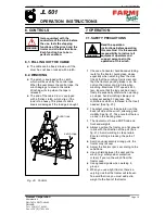
The winch can be mounted to the 3---point
linkage of any tractor. Power transmission is
obtained through universal shaft from tractor.
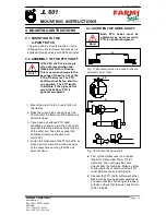
4.2. ASSEMBLY OF THE PTO SHAFT
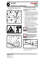
If the PTO shaft is too long it
may get pressed when the
three point hitch is lifted up.
This may cause damage to the
bearings of the winch or to the
PTO of the tractor. The PTO
shaft must not be too short in
any position. The PTO length
is suitable, if the pipes do not
reach the bottom. PTO is
optional equipment.
Note!
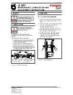
1. Mount the winch to the 3---point hitch of
the tractor.
2. Raise the winch high enough to get the
PTO shaft of the tractor and the winch to a
horizontal level.
3. If you have a shortened PTO shaft
available, put one end into the drive shaft
and check that the distance of the locking
of the other end. Take into account the
additional clearance of approx. 20
mm(0.78”).
4. Fasten the other end of the PTO shaft in its
place and also move the winch sideways
at the same time securing that the axis
does not base.
4.3. SHORTEN THE DRIVE SHAFT
Both PTO halves must be
shortened by equal amounts.
PTO is optional equipment.
Note!
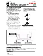
A
Fig. 17.Measure A when the drive shafts are
nearest to each other.
A
20
1
2
Fig. 18.Shorten the drive shaft.
D
First cut the thicker cover to a correct
lenght (1). Remember 20mm (0.78”)
clearance. Then cut away the same
amount from the form pipe. Make a similar
shortening to the second half of the PTO
shaft. Remove the burr with the file.
D
Connect the PTO shafts within each other.
Make sure by moving eevator carefully up
and down that the shortening of the axis is
sufficient. Check that the axis have 20mm
(0.78”) latitude.


