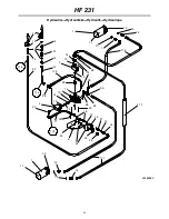
HF 231
10
6.MOUNTING
1. The hydraulic feeder and mechanical feeders
include fitting blocks that are installed between the
chipper and feeder.
The fitting blocks are installed so that the two guide
pins located at the bottom section of the feed
opening go through the holes in the fitting block and
secure the block. See Fig. 2.
Fig. 2.Installing the fitting block.
2. Attach the feeder frame to the chipper pins and lock
bolts. Fig. 3.
Fig. 3.Mounting the feeder on the chipper.
3. Attach the feed chute to the frame with two M10x110
bolts and lock nuts. Fig. 4.
Fig. 4.Installing the hinge bolts.
4. Lock the chute in the operating position.
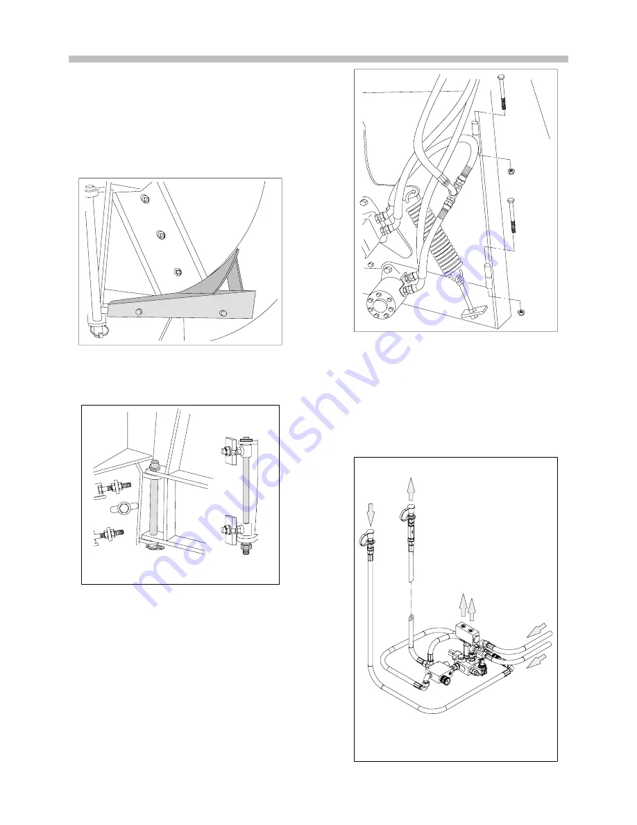
5. Connect the hydraulic hoses. Connect the pressure
hose (P on the valve) to the pressure connector of
the tractor’s hydraulic system. The maximum
operating pressure is 175 bar. Connect the return
hose (T) to the return connector of the
double---acting valve, or preferably directly to the
tank. Fig. 5.
T
P
Fig. 5.
Connecting the hydraulics, feed.
Summary of Contents for VALBY HF 231
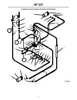
Page 13: ...HF 231 13 10 HYDRAULICS CIRCUIT DIAGRAM Fig 12 43484050...
Page 14: ...HF 231 14 HF 231...
Page 16: ...HF 231 16 HF 231...
Page 27: ...27...
Page 28: ...28...
Page 31: ......
Page 32: ......


