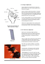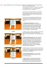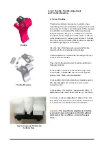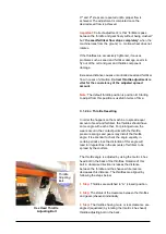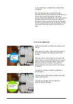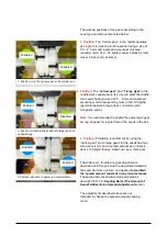
B.4. Tracking System Connection
The equipment and sensor necessary to use of the
system in the models with tracking system come as
assembled on your grain drill.
The installation procedure steps you need to follow to
use the system over tractor are described below:
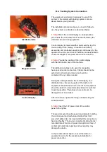
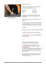
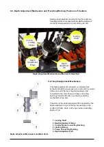
Distribution Box
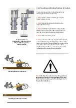
Magnetic Clutch
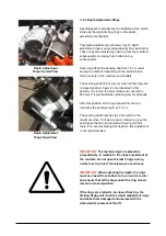
Control Display
1. Step:
Mount the control display on an appropriate
point inside the cab where it will not be affected by the
vibrations to occur during operation.
Control display is delivered with metal mounting leg. For
the mounting of the display, a location that is easily
accessible and controlled visually and continuously by the
operator should be preferred. In addition, areas exposed to
constant sunlight or rain water should not be chosen.
2. Step:
Provide the cabling of the control display
with the distribution box on the machine.
The distribution cables to be used for connection
have special socket connectors. Cables should not be
extended or shortened and service should be
contacted for any cables needed.
During the cabling between the control display and
distribution box, the moving parts of the tractor and
equipment should be taken into account and equipment
should be able to be mounted easily when it is switched
to parking position. The places where cable can be
damaged must be avoided.
After connection, tighten the fixing nut interlocking the
socket and slot.
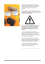
3. Step:
Insert the 12V power inlet of the control
panel to the lighter.
The system meets the entire power requirements including
the control panel and mechanical clutches from this 1
piece 12V lighter inlet. It is important that this connection is
fixed and healthy. The device is capable of storing the last
recorded data at the time of power interruptions or loss of
contact but instant deenergizing and reenergizing may
damage the device.
In the models without lighter, consult the tractor or
equipment service for the necessary installation for
power connection.
Summary of Contents for FDD 2500
Page 1: ......
Page 103: ...Seed Calibration Quick Reference Guide To ensure accuracy always do a manual calibration test ...
Page 104: ......
Page 105: ......

