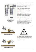
4.
Step:
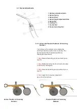
Lower the marker arm slowly.
5.
Step:
Apply the 4 procedure steps given above for
the other marker arm by taken the safety warnings into
account.
Note:
The arms may not be lowered to bottom position if
compressed oil remains in the marker lifts. In such case,
lower the arm to the ground by using the hydraulic
controls guiding the market lifts on the tractor.
6.
Step:
After the work, you can switch the markers to
travelling position by implementing the procedure
steps given above in reverse order.
IMPORTANT:
Do not apply hydraulic force to locked
marker arms. This may lead to damaging of the lock
bolt, bolt slot and/or hydraulic elements.
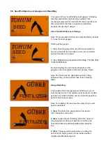
C.4.4 Speed Adjustment of Marker System
You can customize the working speeds (lowering-lifting) of the
marker discs according to the tractor pump flow rate or your
working habits.
IMPORTANT:
Before the adjustment, the hydraulic
connections of tractor and marker system must be made
and the markers must be switched to working position.
Before the procedure, ensure that you made the
preliminary preparations mentioned above.
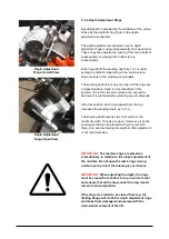
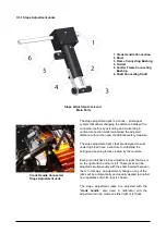
Marker speed is adjusted based on
following procedure steps:
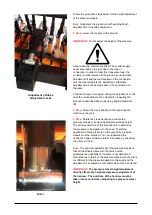
1. Step:
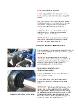
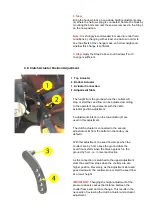
Insert the Allen wrench no. 6 in the set screw
on the speed control valve.
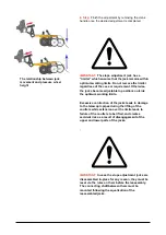
2. Step:
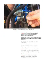
Lower and lift a marker arm regularly and
subsequently by using the hydraulic controls on the
tractor.
Insertion of Allen Wrench in Set Screw
IMPORTANT
:
The factory set (default) speeds of the
markers may not be consistent with the pump flow
rate of your tractor. If there is such an inconsistency,
the markers will move too fast or too slow at the time
of initial drive (In some cases they may not move).
Thus, choose a low speed as possible when you are
to drive the marker arms for the first time.
Summary of Contents for FDD 2500
Page 1: ......
Page 103: ...Seed Calibration Quick Reference Guide To ensure accuracy always do a manual calibration test ...
Page 104: ......
Page 105: ......

