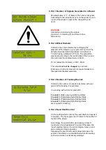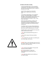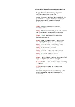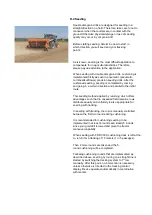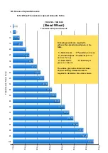
C.10.2.1 Number of Signals Generated in a Round
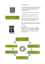
Its default value is “1”. It refers to the number of signals
transmitted to the inductive sensor on the wheel in each
round of the wheel. It must not be changed by end
users.
WARNING:
Increasing or decreasing the values:
Up Arrow
– Increasing (4) and Down Arrow -
Decreasing
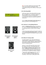
C.10.2.2 Wheel Diameter
It refers to the value obtained by multiplying the
diameter of the wheels on your grain drill by 0.62. The
default value was determined based on a wheel of
7.50-16 having a diameter of 76 cm. The calculation
was made according to the round ratios of the tire and
the clutch and the constant value is 48 cm.
76 cm (actual tire diameter) x 0.62 = 48 cm
This value
must not be changed
by end user.
Entering an incorrect value will not cause deviations in
the speed and treated area data.
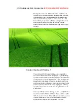
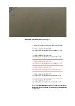
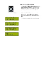
C.10.2.3 Number of Tracking Rounds
It refers to the number of rounds to be taken with your
grain drill for tracking. For example:
In a seeding with a 3-meter grain drill;
3 rounds
for
9-m
spraying-fertilizing drillers
4 rounds
for
12-m
spraying-fertilizing drillers
5 rounds
for
15-m
spraying-fertilizing drillers
6 rounds
for
18-m
spraying-fertilizing drillers
are required for tracking.
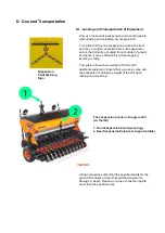
C.10.2.4 Seed Shaft Control
It is the setting which controls the seed shaft and reports it
to operator. The figure given as 25 refers to the number of
rounds of the wheel.
Accordingly, the seed shaft must rotate by at least 1
round when the wheel takes 25 rounds. Otherwise, the
“seed” warning light on the control display turns on and
gives visible warning to operator.
Increasing the seed shaft control value decreases the
system’s sensitivity to a potential fault while decreasing
such value causes unnecessary warnings.
Summary of Contents for FDD 2500
Page 1: ......
Page 103: ...Seed Calibration Quick Reference Guide To ensure accuracy always do a manual calibration test ...
Page 104: ......
Page 105: ......


