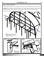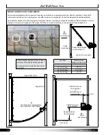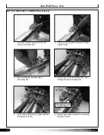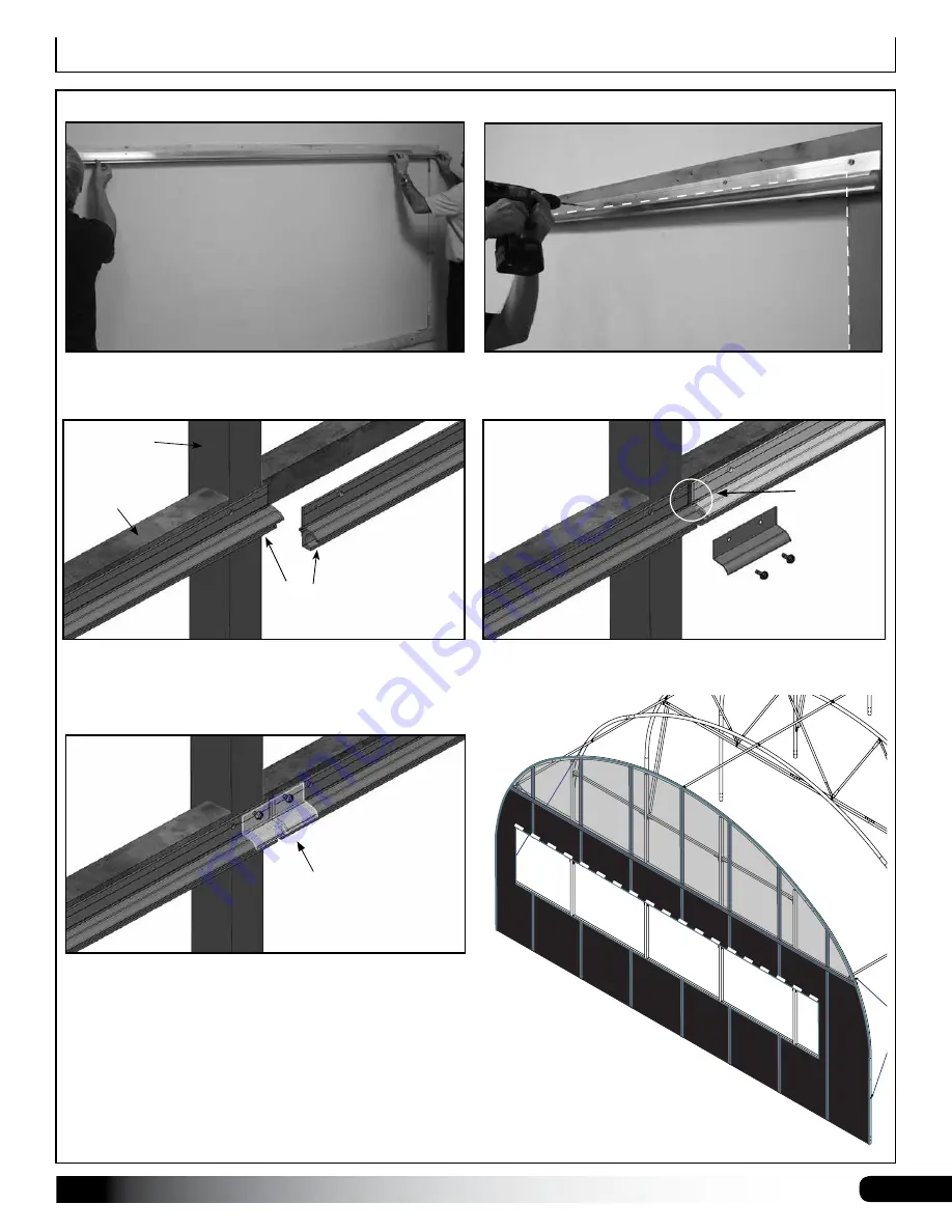
11
Revision date: 03.08.17
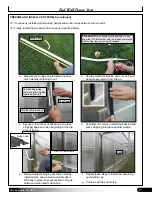
a. Center vent sash above opening.
b. Secure vent sash to building with FA4484B
Teks screws and 102921B neo-bonded washers.
Diagrams show a vent system with multiple sections. Hinge, top, and bottom rail sections are connected using a splice.
This is an example of a vent sash splice. Actual building frame member may differ from what is shown.
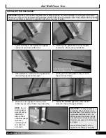
c. After installing vent sash, coat seam and splice surface
with DE4007 silicone sealant. Center and attach vent
sash splice (111614SPL) using FA4484B screws.
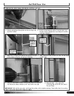
d. Line the top edge of the entire run of 11614Z144 vent
sash with a thick bead of DE4007 silicone sealant to
prevent water leakage.
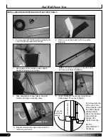
Installed Splice
111614Z144
Vent Sash
End Wall
Column
End Wall
Cross Beam
Align vent sash with
finished vent opening as
shown. See dashed line.
FA4484B
Tek screws
To seal the
splice, coat
area with
sealant after
rails are
attached
and before
splice install.
End Wall Power Vent
ASSEMBLE VENT FRAME (continued)
White dashed line indicates installation
location of the 11614Z144 vent sash. Cut to
fit vent sash sections as needed.
NOTE:
Polycarbonate removed from diagrams for clarity.


