27
Revision date: 03.08.17
The photos and procedures that follow describe the installation of typical vent drive components. A sample vent is used to present a
typical system
with the drive motor mounted outside the main building. Use this information as a basic guide during the assembly
of purchased vent system.
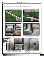
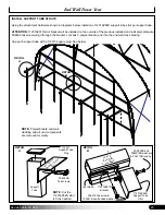
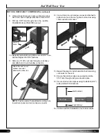
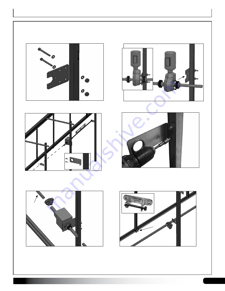
1. Attach 115069 mounting plate to the support tube.
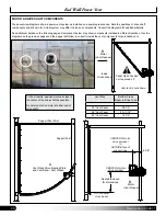
See tables on previous pages for dimensions.
2. Secure motor with attached chain couplings to
mounting plate. Tighten bolts using a ratchet & socket.
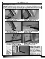
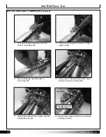
3. Determine positions of 111674 vent bearing plates
on support tubes. Use drive shaft pipe and a level
to ensure that vent bearing plates are aligned with
motor sprockets.
4. Mark plate position and secure plates to the support
posts. Use FA4482 Tek screws.
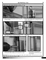
5. Slide 1.315" drive shaft tube (131S147) into place and
verify that it turns freely in all bearing plates.
6. With assistance, remove drive shaft and slide
111679 vent rack drives onto drive tube between
the 111674 bearing plates.
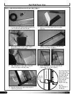
Install one 111679 vent rack drive for each 111681
vent window connector.
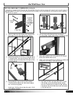
7. Align each 111679 vent rack drive with a 111681
vent window connector attached to the bottom
rail of vent window frame. Attach 111681 window
connectors using
FAG102B bolts, FAME16B washers
& FALF15B lock-nuts.
111674
Align bearing
plate with motor
.
1
111681
1
111679
Drive
Shaft
MOTOR & DRIVE SHAFT COMPONENTS (continued)
End Wall Power Vent
Support Post
115069 Plate
FAG363B
Bolts
FAME08B
Washers,
FAMA38B
Lock-Washers
& FALB04B
Nuts
Motor


