31
Revision date: 03.08.17
Regular inspections of your vent systems helps to ensure
dependable, safe, and efficient operation. Complete
the following inspections at least once every 30 days.
If
weather and environmental conditions are extreme in
your area, inspect the vent system more frequently.
ATTENTION:
When severe weather is expected, close
vent and secure in place to prevent damage to building
contents, vent frame, and related components. Always
inspect your vent system after severe weather events and
before using.
Motor Care and Maintenance
Disconnect main power before inspecting the drive
motor, related drive components, and vent frame.
Vent Frame Inspection
•
Inspect weep holes in bottom rail. Clean when
necessary to allow condensation to drain from
polycarbonate panels.
End wall vent only.
•
Verify that all mullion cap screws are tight.
End wall
vent only.
•
Check all bolt and nut fasteners to ensure these
remain tight.
•
Tighten all vent window connector mounting bolts.
Check and tighten connector to vent rack mounting
bolt.
•
Check maximum vent travel to ensure that it does not
exceed 40° when fully open. Adjust as needed.
Drive Motor and Related Components (if equipped)
•
Check vent travel. Reset limiting switch settings to
properly regulate vent operation.
•
Check mounting bracket and bolts for drive motor.
Verify that all are tight.
•
Lubricate rack and vent rack drive gear using a
general multi-purpose grease.
•
Check all rack drive set screws regularly to ensure
these remain tight.
•
Inspect drive chain and sprocket. Clean and lubricate
as needed.
•
Visually inspect all electrical connections. If electrical
issues exist, disconnect main power and contact an
electrician to inspect and repair if necessary.
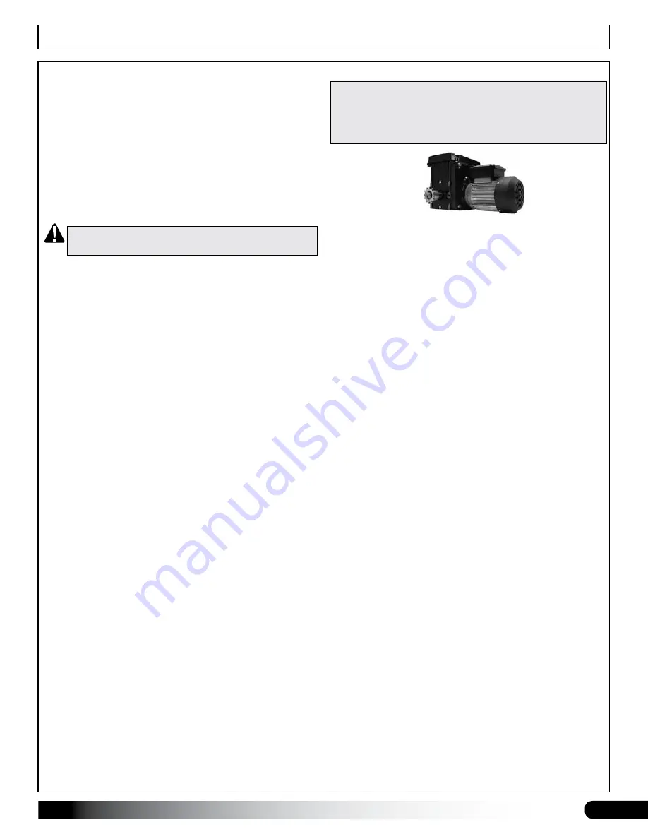
If you are assembling a motor-driven power vent system that
includes an electric motor and related drive components,
continue with the information on the following pages. Consult all
drawings for your power vent system before you assemble drive
components and attach assemblies to the vent.
MOTOR-DRIVEN POWER VENT SYSTEMS
GENERAL SEQUENCE OF POWER VENT
COMPONENTS
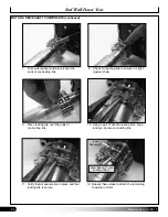
1. Attach chain bolt coupling(s) to motor as shown in
this guide.
2. Mount motor to end wall supports, rafters, or rafter
chords. Consult diagrams. Adjust accordingly for
ridge vent, end wall vent, and blackout system
installations.
For all vents, create two drive tubes of similar length
and center motor between separate tubes.
Do not
mount drive motor at end of vent drive train.
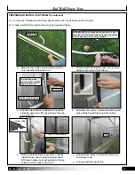
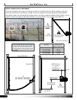
3. Determine locations of 111681 vent window
connectors (ridge and end vent only) and attach
these to bottom rail of assembled vent frame.
Consult diagrams.
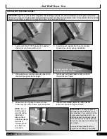
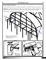
4. Determine the locations of the 1.315" drive tube and
111674 vent bearing plates.
5. Attach vent bearing plates to the underside of the
rafters (ridge vent), or to support posts driven into
site (end wall vent).
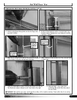
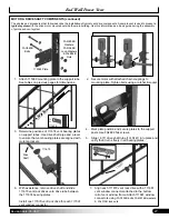
6. Take assembled drive tubes, slide 111679 vent rack
drives onto tubes as you slide each tube through
vent bearing plates. Slide plain end of each drive
tube into chain bolt coupling attached to motor.
ATTENTION:
Each rack (111673) will attach to a
vent window connector and requires a vent rack
drive.
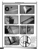
7. Slide each rack through vent rack drive and attach
rack to vent window connector.

