78
Revision date: 12.02.16
,167$//5$&.'5,9(6
Black-out System Installation
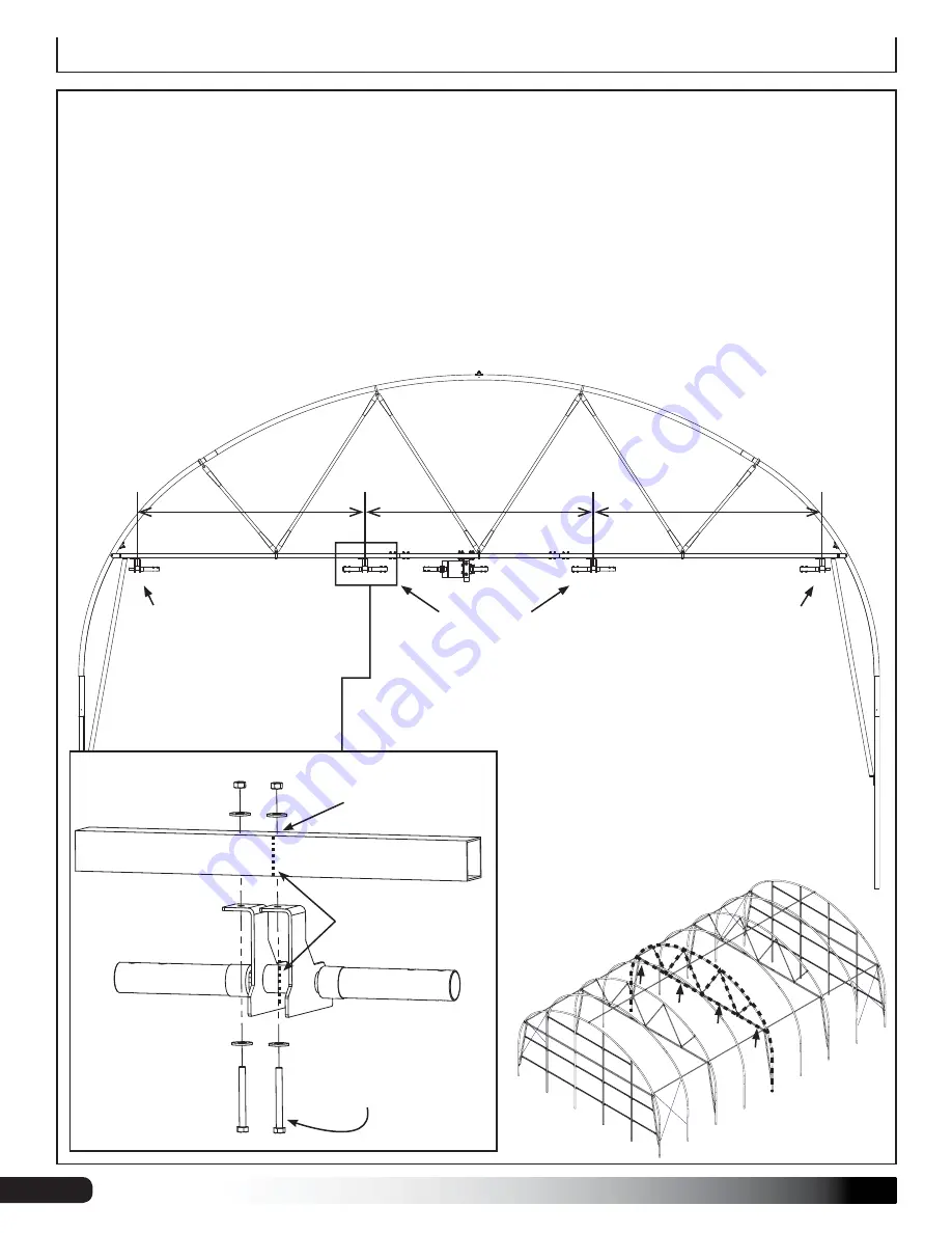
1. Measure and mark the locations for the rack drives as shown below. Measurements shown indicate the CENTERS
of the rack drive gears.
ATTENTION:
It is important that the "left" and "right" rack drives be installed as far to the outer corners as possible
without running interference with the vertical header.
IMPORTANT:
Due to potential obstructions, it may be necessary to off-set a rack drive slightly one way or the other.
This is acceptable to adjust accordingly, but it is important NOT TO EXCEED 8'-8" between any two rack drives.
2. Using the rack drive holes as a template, mark and field drill the attachment holes.
3. Using 5/16" x 3" bolts (FAG338B), 5/16" flat washers (FAME07B) and 5/16" lock nuts (FALF37B), attach the rack
drives to the underside of the "power rafter" as shown below.
DO NOT TIGHTEN AT THIS TIME.
RIGHT
Rack Drive
(**see orientation note)
CENTER
Rack Drives
**ORIENTATION NOTE:
View as seen from the
end wall with the 113650
wire tensioners,
looking
towards
the end wall with
the 113694 brackets.
LEFT
Rack Drive
(**see orientation note)
5/16" x 3" bolt (FAG338B)
5/16" flat washer (FAME07B)
5/16" lock nut (FALF37B)
Pre-drill attachment holes in
the center of the rafter chord.
2"x2"
Power Rafter Chord
Align the center of the
rack drive gears with the
previously marked rack
drive location.
IMPORTANT:
Rack
drives are oriented
towards end header
with 113694 brackets
attached, and are in
line with the motor
drive shaft couplers.
8'-8"
8'-8"
8'-8"


