93
Revision date: 12.02.16
Black-out System Installation
ASSEMBLE AND INSTALL DRIVE PIPE COMPONENTS
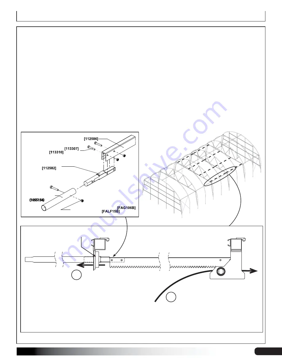
1. Attach a 112582 rack drive coupler to each end of the four (4) 112586 rack arms using 113307 bolts & 113310 nuts.
NOTE:
Square ends of the couplers will sit inside the rack arms as shown below.
2. At one end of each rack arm, add a 13' section of drive pipe (105S156). Splice the
plain
ends of the drive pipe onto
the rounded, open ends of the 112582 couplers using 1/4"x1-1/2" bolts (FAG106B) and 1/4" lock nuts (FALF15B).
3. With assistance, or a lift machine, hoist the rack/pipe assembly into one rack drive, with the teeth of the rack arm
facing DOWN to marry up with the rack drive gears. Push the rack/pipe assembly through the rack drive until the
the swaged end of the pipe section is able to be guided through the drive roller on the next rafter (see #1 & #2 in
diagram below). Position so that the weight of the rack/pipe assembly is fully supported by the rack drive and the
drive roller. Repeat for each rack drive location.
ATTENTION:
Depending on greenhouse length, it may be necessary to have to splice the pipe end of this rack/
pipe assembly with the previously installed drive pipe that is sitting loosely on the telescoping purlin. See following
pages for details.
RACK ARM DRIVEPIPE
COUPLING
-(2X) M6 X 25MM BOLT
-(2X) M6 NUT
RACK ARM
-(1X) 1/4" X 1-1/2" CAP SCREW
-(1X) 1/4" LOCKNUT
1.05" DRIVEPIPE
(105S156)
1
2
Guide the rack/pipe
assembly up through
the rack drive until the
swaged end of the drive
pipe has cleared the drive
roller on the next rafter.
112588
Rack Drive
112586
Rack Arm
105S156
Drive Pipe
CUT-AWAY
SIDE VIEW
112581
Drive Roller
Once the rack/pipe has
cleared the drive roller,
pull the swaged end of
the pipe back through
the drive roller. Guide
through until the weight
of the rack/pipe is evenly
supported by the drive
roller and the rack drive.


