background image

9

Revision date: 03.21.18  

115295

2

ASSEMBLY NOTE:

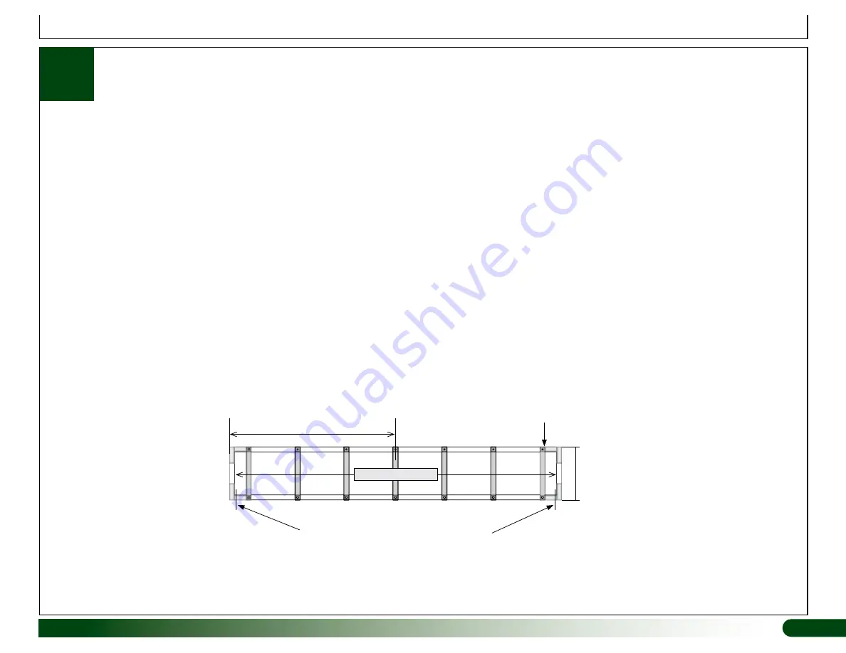
 During frame assembly, set inside-to-inside dimensions at 96-1/2" to 97". Do not seat tube tight to the inside of corner fittings. Doing 

so will result in a dimension too narrow to accept 96" lettuce rafts once liner is installed. 

When setting inside dimensions always evenly divide space 

between corner fittings. At least 2" of any tube must remain within a coupler, fitting, or other tube.

*Not to scale.

16”

Sample End Wall

104779 Tube

Install vertical tube 

tight against the 

3-way corner insert.

Ends of upper and lower tubes are 

1/2" from being fully seated in fittings.

Center in End Wall

97" Inside-to-Inside

Raft Bed Assembly

ASSEMBLY STEPS

Follow these general steps when constructing raft bed:
1.  To minimize possible damage to liner, install all fans, heaters, and lighting (including wiring) that will be positioned above raft bed 

before

 assembling bed.

2.  Frame cannot be moved once assembled. Take the necessary steps to keep frame square during assembly. 
3.  Clear site of debris and obstacles that could hamper construction progress.
4.  Level the surface where raft bed will be located. 
5.  Read all assembly steps for raft bed to better understand parts layout.
6.  Separate parts and set aside (if this has not been done) to prevent confusion and mixing of parts during construction.
7.  Secure all tube and fitting connections using FA4572 Tek screws.
8.  Install Tek screws in positions that will not contact bed liner when it is installed.

Summary of Contents for Growers Supply HydroCycle

Page 1: ...vision date 03 21 18 Actual system may differ from example shown 115295 AQUAPONIC SYSTEM I 2018 Growers Supply All Rights Reserved Reproduction is prohibited without permission HydroCycle Aquaponic Systems ...

Page 2: ...is manual to better understand the different assembly procedures Review Table of Contents left column 2 Determine basic system layout and placement in building 3 Locate raft bed liner and move it to a safe location until installation 4 Set stands and tanks in place 5 Take inventory of all plumbing parts and PVC tubing 6 Separate and inventory the raft bed parts 7 Begin assembly CAUTION Tanks are h...

Page 3: ...ing smaller parts such as fasteners or washers if equipped WARNING Enlist the services of an experienced electrician when connecting power to the pump and other electrical devices All wiring to be completed according to established codes and practices DROWNING HAZARD Never allow children or others within the boundary of the tanks raft bed and pump stations at any time Always have an assistant pres...

Page 4: ...pes of fish and plants Since the specifics of such an undertaking have filled many books it is best to determine beforehand exactly how you want to use this system Water quality location growing environment available resources personal knowledge and experience among other things all must be considered before populating system with plants and fish Consult with your sales representative for addition...

Page 5: ...talling plumbing Due to weight it is recommended to assemble stand in the area where the system will operate Stand is not easily moved once assembled When setting tank stands orient stand so support legs allow easy installation and routing of plumbing as shown in diagrams and photos IMPORTANT WINDOW KITS FOR FISH TANKS If window kits were purchased for the 125 gallon fish tank install those before...

Page 6: ...lanning where to position your system inside the building Review all diagrams and photos in this guide before you begin ATTENTION Diagram below shows recommended system layout Increasing distance between tanks or between tanks and raft bed will require the purchase of additional PVC tubing and fittings Top View Actual pump may differ Pump Station Bulkhead Plate ...

Page 7: ...ightly from those shown ID AQUAPONIC SYSTEM I MAIN COMPONENTS A 125 GALLON TANK 115318 STAND See Section 4a to assemble B RADIAL FLOW CLARIFIER 15 GALLON TANK 112732 LID 115304 TANK STAND 116062 C MINERALIZATION TANK 15 GALLON TANK 112732 TANK STAND 116062 D RAFT BED See diagram for inside to inside dimensions E MAIN WATER PUMP 113536 AND BULKHEAD PLATE AQ139 LOCATION SYSTEM FOOTPRINT APPROXIMATEL...

Page 8: ...sh to top of 3 way fittings 110611 3 Way Insert All Corners S15P016 Tube 16 All Corners Install flush to top of 3 way fittings Sample End Wall 104779 Tube Install vertical tube tight against the 3 way corner insert 16 Diagrams below show layout of assembled 8 x 8 raft bed Use these diagrams and dimensions as guides during raft bed frame assembly The inside to inside dimensions allow room for liner...

Page 9: ...nside to Inside Raft Bed Assembly ASSEMBLY STEPS Follow these general steps when constructing raft bed 1 To minimize possible damage to liner install all fans heaters and lighting including wiring that will be positioned above raft bed before assembling bed 2 Frame cannot be moved once assembled Take the necessary steps to keep frame square during assembly 3 Clear site of debris and obstacles that...

Page 10: ...e steps 1 Construct main frame using corner fittings and the upper and lower tubes 2 After perimeter frame is assembled install vertical supports Secure each support to upper and lower tubes using two 2 FA4572 Tek screws for each beveled support Use photos below and diagrams on previous pages to assemble one 1 8 x 8 raft bed frame 16 Install vertical tube tight against 3 way corner and 3 way tee f...

Page 11: ...en dimensions are the same frame is square Be sure to measure from same points at each corner Finally level frame Frame must be level so water depth is consistent throughout frame once raft bed is filled Prepare site inside the raft bed frame if not on a solid surface such as wood or concrete ATTENTION Actual frame may differ from what is shown Procedure to square frame is the same Raft Bed Assemb...

Page 12: ...plete these steps 1 Once frame is level insulate frame bottom Frame shown below may differ from actual frame 2 Cut insulation board as needed to fit side and end walls 3 Continue with the installation of bulkhead plate used to connect main water pump Raft Bed Assembly ...

Page 13: ...removed to better show installation of pump plate Use parts identified at right to install bulkhead plate Review Section 1 diagrams for location ATTENTION Install bulkhead plate opposite where mineralization tank flows into raft bed Additional 112375 support to secure insulation After attaching plate to inside of frame using four 108553 wafer head screws attach another beveled support Use a utilit...

Page 14: ... of raft bed size follow these general guidelines Maximum length of any tube loop should not exceed 300 Loops must be of equal length Consult the services of a qualified contractor familiar with installing similar heating systems If you purchased components to heat your aquaponic system install tubing in raft bed before liner installation See note above After installing raft bed tubing for heat if...

Page 15: ...e rails NOTE Ensure liner is fully seated in corners and on bottom before installing fasteners These are removed later in procedure 3 Fold liner evenly up and over top of frame rails Remove as many wrinkles as possible Do not crease liner material 5 Move to another corner and press liner into place Required parts Raft Bed Liner FA4572 Tek Screws 102921B Washers and 100442 Nut Setter ATTENTION Duri...

Page 16: ...o raft bed to allow water to seat liner inside frame NOTE Do not fill more than 1 2 Water level to stay below hole in bulkhead plate 12 Fill bed with 1 2 of water Water level to remain below hole in bulkhead plate 2d 13 Install pre drilled aluminum retaining strap 6 Cut material as needed to allow it to fit more evenly at corners ATTENTION Do not drop any sharp objects into bed liner at any time C...

Page 17: ...aps to frame until entire perimeter of bed liner is secure NOTE Remove temporary Tek screws and washers before installing aluminum straps 6 Install 112770 finishing plug at each corner when liner is secured 3 Grip edge of bed liner with duck bill locking pliers or similar tool 7 Using a utility knife or scissors remove excess bed liner material Allow 1 or so to remain beyond the edge of aluminum s...

Page 18: ...r bulkhead body 3 Remove liner material after cutting 7 Add large locking nut and tighten until snug 5 From the inside insert bulkhead fitting through hole in liner and through bulkhead plate ATTENTION Photos show installing a larger bulkhead in a different raft bed Installation steps are the same for the 1 1 2 fitting used in this raft bed Complete these steps to install the 1 1 2 bulkhead fittin...

Page 19: ...tands on raised blocks or platforms IMPORTANT To ensure proper water levels throughout the system during operation set tank stands on the same finished grade as the float bed Review layout diagrams for additional details To best judge raft bed position and to ensure economic use of available space and PVC pipe assemble if needed and set all stands in place to get started Section 1 Review diagrams ...

Page 20: ...4 Tighten using a 7 32 Allen wrench Verify that bolt holes for struts are oriented so struts align with mounting holes See diagrams on next page ATTENTION Mounting holes on legs are in different positions If legs are installed incorrectly mounting holes in struts will not align with mounting holes in frame top Use a strut to match hole locations during leg installation Rotate leg as needed and tig...

Page 21: ...earlier as guides Remember to orient stand so plumbing when installed does not contact stand support legs 7 Using a level minimal 4 adjust feet as needed to level stand Keep stand height as low as possible Do not over extend adjustable feet For best results height of deck from finished floor is approximately 24 after stand is leveled 8 When level tighten locking nut on each adjustable foot 9 Conti...

Page 22: ...ing the layout diagram set and level tank stands for the radial flow clarifier tank and mineralization tank TOP VIEW Align tank stands Centerline 12 4 3 4 6 12 Raft Bed 4b Assemble Set Tank Stands DIAGRAM NOTE TANK STANDS Actual tank stands may differ from those shown in diagrams Assembly of system remains the same ...

Page 23: ... Using tank diagrams lower right and the correct hole saw bit drill a hole in the center of each tank bottom Verify hole saw bit size before drilling ATTENTION Drill a 2 1 4 hole in bottom of the 125 gallon tank to install the 1 bulkhead fitting Drill a 3 hole in bottom of each 15 gallon tanks to install 1 1 2 bulkhead fitting Top View 125 Gallon Tank 2 1 4 Hole Top View 15 Gallon Tank 3 Hole 2 Af...

Page 24: ... Fittings WF8582 1 WF2193 Adapter 1 2 3 1 3 Install assembly tighten lock nut and tighten adapter fitting NOTE Some bulkhead fittings include only a thick rubber washer Threads on fittings are reversed Review diagrams below and install bulkhead fittings NOTE Tanks have a specific bulkhead assembly Confirm that correct fittings are used when installing these fittings See diagrams In most instances ...

Page 25: ... tank 3 Using a 2 1 2 hole saw and drill drill a hole in tank at mark made in previous step Mark will be below tank collar as shown 4 Clean debris from around hole and gently press UniSeal into hole from outside tank NOTE Do not use sharp tools to install Doing so can damage seal and tank surface Lubricate with soapy water if needed 5 After installation inspect seal inside and outside tank to ensu...

Page 26: ...tank See diagram in Section 1 for clarification 4 Using diagram below mark upper hole locations on each tank See diagram Hole locations will be immediately across from each other when marked properly These holes are directly opposite lower side hole in radial flow clarifier tank 5 Take a drill and a 3 hole saw bit and drill one hole in each tank 6 Prepare clean all holes for bulkhead installation ...

Page 27: ...on tank Ensure location will allow for installation of bulkhead WF2198 adapter and related outlet plumbing Review all diagrams for additional details 5 Install bulkhead and two 2 adapters one inside and one outside of tank in outlet hole in mineralization tank 6 Continue by installing plumbing 5d INSTALL BULKHEAD AND ADAPTER FITTINGS SMALL TANKS Prepare Tanks Install Fittings Radial Flow Clarifier...

Page 28: ...STALL SYSTEM PLUMBING Use the diagram below and on the following pages to install system plumbing See list for parts and materials TOP VIEW 12 4 3 4 6 12 Raft Bed Recommended Spacing Supply Line from Pump Station Flow Flow Flow Flow Flow Flow Return Flow to Raft Bed ...

Page 29: ...all 1 fittings when needed B B D G G 115314 Install outlet elbow at an angle to better circulate water IMPORTANT Install horizontal pipe level and vertical pipe plumb The 115314 standpipe strainer must sit over bulkhead fitting and tight to tank bottom Cut pipe to length and glue all standpipe connections Standpipe with 115314 Strainer attached to bottom NO GLUE Dashed line identifies section belo...

Page 30: ...s or Socket Set After constructing the vertical supply tube secure it to the tank as shown 1 Center clamp on tank collar and mark hole location 2 Drill 5 16 hole through tank collar for 1 4 bolt installation 3 Attach clamp to tank and tighten bolt until snug See diagram 4 Gently press supply tube into clamp L 112539 Pipe Hanger Top View L From Pump Return Line to Small Tanks Using 1 1 2 PVC pipe a...

Page 31: ...on between 1 1 2 ball valves that does not need glue This allows repositioning of flush tube for maintenance No water flows through this section during operation Apply glue to joints between tank and ball valve only PHOTO Swing drain tube up or down as needed and set bucket under elbow to catch drain water during flushing or draining As noted below fittings between ball valves are not glued Supply...

Page 32: ...es must remain free to adjust as needed to set required water levels DIAGRAM SHOWS CUT AWAY OF SIDE VIEW Standpipe top to be flush to bottom of tank collar Center of Inlet Pipe Finished Floor Standpipe Bottom of Tank Collar Standpipe to remain adjustable Set top at least 1 2 below tank inlet Lower Line Top of Standpipe Raft Bed Flow Flow Flow Flow Upper Line Shows water level flowing into tank G H...

Page 33: ...e in center of 4 end cap WF0013 2 Add cap to one end of tube Do not glue 3 Slide stilling well tube WF4171Z014 through hole in clarifier tank lid Push tube through lid until cap meets tank lid See photos 4 Set assembly in place on radial flow clarifier tank 5 Install separator and shade material in mineralization tank See next procedure Step 2 Add cap to tube Step 3 Slide tube through tank lid Ste...

Page 34: ...shown below 2 Take the 103761 shade material and roll it out on a clean flat surface 3 Loosely fold material and stuff into mineralization tank as shown below NOTE Shade material provides additional surface area for beneficial bacterial growth 4 Continue with the next procedure Shade Material Cut Away Side View Step 2 Separator Step 3 Shade Material Separator Mineralization Tank Out Step 1 Separat...

Page 35: ...1 2 K 113536 Tiny Might Pump M 113537 Union for 113536 Pump N Use WF4140 1 1 2 PVC pipe General Assembly Notes Apply 113372 primer to all slip joints before applying PVC cement See strainer note for exception Double check all dimensions before cutting PVC pipe All slip joints are glued except as noted Top view showing strainer installed inside raft bed Attach directly to bulkhead Hand tighten only...

Page 36: ...ing from pump station to large tank vertical supply tube Using parts shown at right connect pump station to vertical supply tube Plumbing Fittings and Materials WF1982 Coupling 1 1 2 not shown WF1574 SxS 90 Elbow 1 1 2 G Use WF4140 1 1 2 PVC pipe to construct the supply line Pump Station Supply Tube Supply Line G G G ...

Page 37: ...nstall air pumps above water level in tank s and raft bed as shown See diagram on the next pages All wiring to be in compliance with recognized and established building and electrical codes WARNING Enlist the services of an experienced electrician when connecting power to pumps and other electrical devices All wiring to be completed according to established codes and practices DROWNING HAZARD Neve...

Page 38: ...s to run continuously when system is in operation Do not connect air pumps to a timer or circuit controlled by a switch ADDITIONAL AIR HOSE After installing air stones in fish tank use remainder of hose to connect air pumps to main air stone manifolds Example shows one way to connect air pumps Purchase additional hose locally or contact your sales representation if more is needed In place of the s...

Page 39: ... and slide an AQ116 stone onto one end of each hose 2 Using diagrams and photos on this page evenly space hose and stone assemblies around tank and connect using WF0021 barb tees and short hose sections 3 Position final tee barb in a location that allows easy connection to main air line from air pump 4 Secure entire assembly to tank collar using clamps and FA4572 Tek screws 5 Repeat for remaining ...

Page 40: ...F WF2049 Brass Adapter I x M 3 8 x 3 4 G WF2160 Adapter S x F 3 4 x 3 4 H 106808 3 4 Pipe Hanger and FA4572 Tek Screws I WF4130 3 4 PVC J General Assembly Notes Apply 113372 primer to all slip joints before applying PVC cement Double check all dimensions before cutting PVC pipe All slip joints are glued except as noted Do not apply thread sealant to threads on stones J D E Vertical air pipe to con...

Page 41: ...al tubes Complete these steps 1 Take a 5 stick of 1 2 PVC pipe and slide a 5 length of 1 2 rebar inside it 2 Using PVC primer glue and 1 2 PVC end caps seal rebar inside PVC pipe Allow to dry 3 Carefully place weight along one air manifold between air stones or on top of tube 4 Secure weight to manifold using a few plastic cable ties 5 Repeat to create additional weights as needed Use one 1 5 weig...

Page 42: ...8 panel A step bit allows for drilling a uniform size hole through the rigid foam board It also allows you to drill a tapered hole that works better for some media Determine which type of hole is needed for your planting needs and prepare the rafts accordingly Experiment with different bits until desired results are achieved For net pots do not use a step bit Step bit is not included Purchase loca...

Page 43: ... the best fit See lower photo Use an anchoring method that is easy to undo to allow access to tank for fish harvest and regular maintenance Rope is included to secure net to tank Suggested parts to cover tanks TC2630A Bird Netting included CC5310 3 16 Black Rope included used to secure bird netting Bird netting covering large fish tank ATTENTION Actual tank and supply valve assembly shown may diff...

Page 44: ...raft beds Cycling Before populating system with fish and plants system must be cycled Cycling refers to facilitating growth of beneficial autotrophic bacteria that will remove ammonia produced by fish Full colonization of systems with bacterial can take 4 6 weeks While system is cycling no plants keep raft beds covered to prevent algae growth One option is to place the polystyrene rafts before dri...

Page 45: ...determine how long it should take to fill a known volume of water If the desired flow into a tank is 20 gallons per minute it will take exactly 15 seconds to fill your bucket to the line Known Volume gallons Desired Flow Rate gpm x 60 15 seconds 5 gallons 20 gpm x 60 If bucket fills faster restrict flow to tank by slightly closing inlet ball valve If it takes longer than 15 seconds slightly open v...

Page 46: ...ted with a balance of fish and plants in mind It is important to adhere to these guidelines in order to maintain that balance The following information is a recommendation of fish stocking and harvesting numbers It serves as a guide to determine fish density at any given time in the system Fish Stocking SYSTEM I 115295 Stock System I 115295 with 40 50 fish of similar size Stocking different size f...

Page 47: ...water flows through both tanks it is clean enough for bacteria in your deepwater culture DWC beds to remove ammonia and convert it to nitrites for plants These autotrophic bacteria grow everywhere in your aquaponic system but are concentrated in DWC beds due to increased surface area below plant rafts and on plant roots Daily Maintenance In order to prevent excess buildup of solids it is important...

Page 48: ... rinsed bunch it back up and place it back into the mineralization tank Ensure that water cannot flow around or bypass the material Water must flow through the material After thoroughly cleaning both filters close all discharge valves below the clarifier and mineralization tanks Once a Week or As Needed Once a week the radial flow clarifier and mineralization tanks filters will need thoroughly was...

Page 49: ...49 Revision date 03 21 18 115295 Customer Notes and Records ...

Reviews: