background image

17 

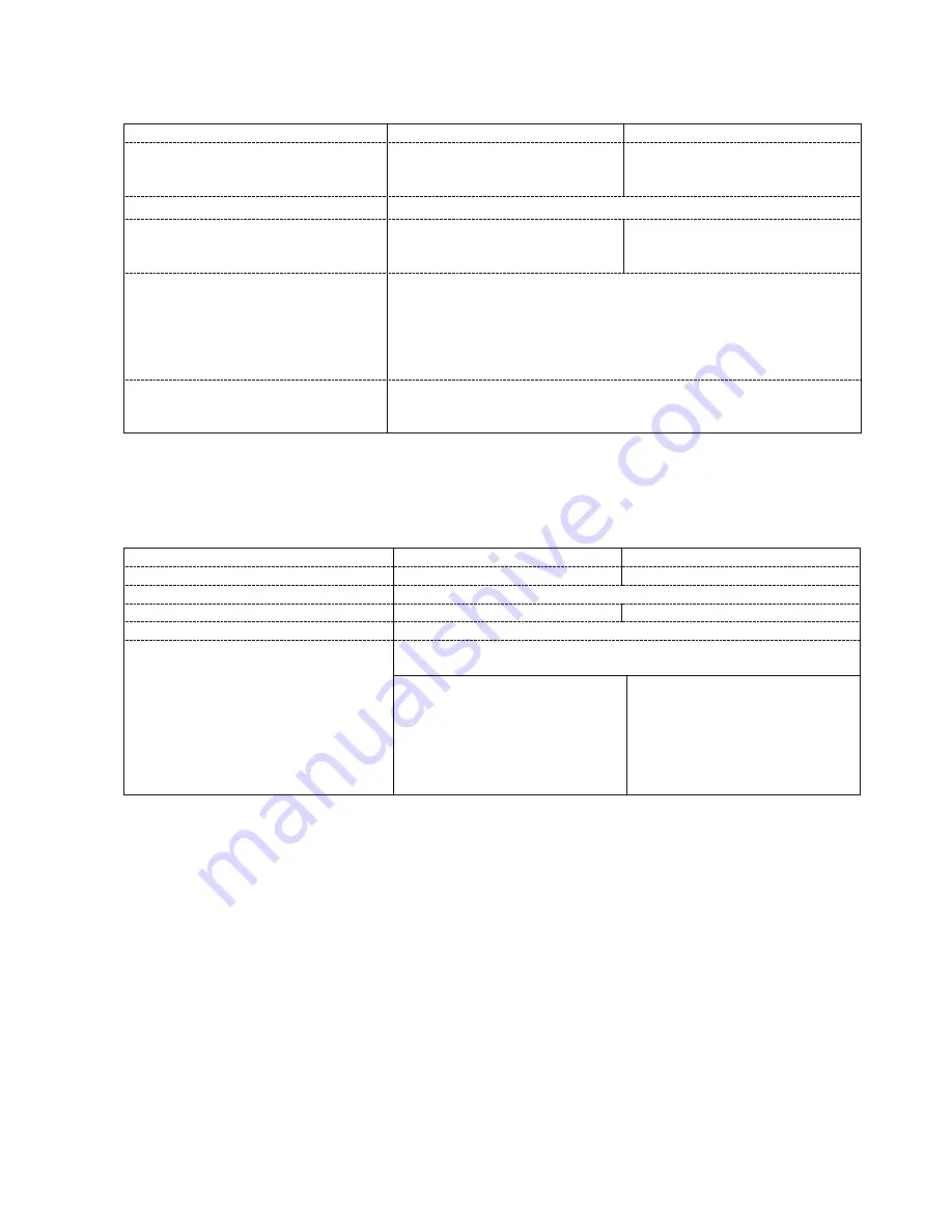
2.10.


Tractor weight. 


Weight of tractor in running order,


kg  

3585 kg 

3308 kg 

Weight distribution on axle, kg:   

  front 

  rear 


1470 kg 
2115 kg 


1204 kg 
2104 kg 

Maximum permissible tractor weight kg 

6000 kg


Weight distribution on axle kg: 

  front 

  rear 


1650 kg 
4350 kg 


1500 kg 
4500 kg 

Maximum mass of the trailer


kg:  

  Unbraked trailer towable mass 

  Unbraked agricultural implement 

  Inertia braked towable mass 

  Independently braked towable mass 

  Towable mass fitted with air braking 


1500 kg 
3000 kg 
5000 kg 
5000 kg 

12500 kg


Ballast weights  


  Front axle 

6 x 22 + 1 x 40 = 172 kg 

  Rear axle 


2 x 39 + 4 x 32 = 206 kg 


2.11. Tractor dimensions.     


Overall length, mm 

3725

4190 mm 

3710

4185 mm 

Overall width, mm 

1939

2375 mm 

1950

2350 mm 

Overall height, mm 

2490

2505 mm 

Wheelbase, mm 

2314 mm 

2413mm 

Ground clearance, mm 

390

405 mm 

Minimum turning circle  without 
independent braking, mm: 


to the left 
front drive engaged 
front drive disengaged 


to the right 
front drive engaged 

   front drive disengaged 

With wheel track: 

front 

– 1560; rear – 1508 


10100 mm 

9350 mm 


9900 mm 
9150 mm 


7710 mm 


7600 mm 


Summary of Contents for 675

Page 1: ...Kullanım Kılavuzu Farmtrac 675 675DT ...

Page 2: ... 4 OPERATION 25 4 1 Tractor running in 25 4 2 Starting and stopping the engine 25 4 3 Driving the tractor 27 4 4 Power take off PTO 28 4 5 Tractor hydraulic system 30 4 5 1 Hydraulic lift system 30 4 5 2 External hydraulics control 32 4 6 Equipment attaching on three point linkage 33 4 7 Attaching trailed machines and implements 36 5 MAINTENANCE AND ADJUSTMENT 37 5 1 Periodic maintenance chart 37 ...

Page 3: ... Tyres use maintenance 51 5 7 5 Wheel bearings greasing 51 5 8 Clutch 52 5 9 Transmission rear axle maintenance 53 5 10 Three point linkage 53 5 11 Cab and operator s seat 53 5 12 Braking system 54 5 12 1 Service break adjustment 54 5 12 2 Parking brake 55 5 13 Air braking system 55 5 14 Hydraulic lift 58 6 ENGINE FAULT FINDING CHART 59 7 TRACTOR STORAGE 61 8 WIRING DIAGRAMS 62 ...

Page 4: ... parts Ad 3 Always start the engine from the operator s seat Ad 4 Stop the engine and remove the key before you start maintenance or repair operations Ad 5 Keep away from the three point linkage Warning lamps marking 1 2 3 4 5 6 7 8 9 10 11 12 13 14 Ad 1 Alternator charge Ad 2 Engine oil pressure Ad 3 Glow plug Ad 4 Differential lock Ad 5 Turn indicators Ad 6 Headlight main beam Ad 7 Work lamp fro...

Page 5: ...erial number should always be quoted to the Dealer whenever tractor requires service Read this manual carefully and keep it at a convenient place for future reference This manual must be considered as an integral part of your tractor If at any time you require service or advice concerning your tractor do not hesitate to contact your Authorized Dealer He has trained personnel genuine parts and the ...

Page 6: ... A careful operator is the best operator Most accidents can be avoided by observing certain precautions to prevent the possibility of injury or damage The following precautions should be taken to help prevent accidents Read these carefully before operating your new Farmtrac tractor Important 1 Read this Manual carefully and familiarize yourself with all the controls before attempting to operate th...

Page 7: ...quipment and when no equipment is attached Be sure hydraulic couplers are properly mounted and will disconnect safely in case of accidental detachment of the implement 15 Ensure any attached equipment or accessories are correctly installed are approved for use with the tractor do not overload the tractor and are operated and maintained in accordance with the instructions issued by the equipment or...

Page 8: ...the PTO shaft cap when the PTO is not being used 2 Disengage the independent PTO clutch prior the selection of PTO Before stopping the engine bring the PTO selection lever in neutral position and wait for the PTO shaft to stop turning before getting off the tractor to connect or disconnect PTO driven equipment 3 Apply the parking brake and block the rear wheels front and rear when operating statio...

Page 9: ...s tighten the fuel tank cap securely 8 If the original fuel tank cap is lost replace it with an approved cap A non approved cap may not be safe 9 Keep equipment clean and properly maintained 10 Do not drive equipment near open fires 11 Should the fuel catch fire extinguish fire covering it tightly with asbestos blanket canvas sheet or rags or else by pouring sand or soil over the fire Never use wa...

Page 10: ...s responsible for the defect NOTE FARMTRAC TRACTORS EUROPE will not accept responsibility for any claim resulting from the fitment of non approved parts or attachments or unauthorized modification or alteration NOTE Repairs of parts protected with seals can by carried out by an Authorized Dealer only Arbitrary removal or breaking of the seal may lead to warranty invalidation 1 5 Tractor delivery t...

Page 11: ...of the tractor and engine 2 Assemble parts removed for transport 3 Check the tractor against its specification 4 Examine the condition of factory seals 5 Remove water and impurities from water trap and bleed the fuel system 6 Check the liquid level in the cooling system and in screen washer system 7 Check the oil level in all system 8 Check the battery electrolyte level and electrolyte concentrati...

Page 12: ...s 17O BTDC 48 O ABDC 59 O BBDC 75O ATDC Fuel System Fuel Injection pump type make Rotary type 1532 2644C312 2644C339 Governor type make Mechanical DELPHI Max no load speed 2350 50 rpm Injector type injector nozzle type injection pressure Delphi 2645K025 LJBX 6923602 18 4 0 4 MPa Fuel Feed pump Electric Fuel filter Two stage type placed between Fuel Feed pump and F I P Recommended fuel summer inter...

Page 13: ...TO clutch Clutch plate diameter transmission PTO 310 mm 310 mm Pedal free travel Transmission clutch 25 35 mm Actuation Transmission clutch foot pedal PTO clutch hydraulic Gearbox with range lever Type CARRARO mechanical with constant mesh gears Number of gears in gearbox 4 4R Number of reduction gears 3 Total number of forward reverse gears 12 F 12 R Gearbox control manual by means of three lever...

Page 14: ... 89 36 8 03 7 64 7 58 6 45 7 44 6 32 7 50 6 38 7 44 6 32 7 75 6 58 4M 52 46 61 72 11 63 11 06 10 98 9 33 10 77 9 15 10 86 9 23 10 77 9 15 11 21 9 53 1H 59 71 70 25 10 22 9 72 9 65 8 20 9 46 8 04 9 54 8 11 9 46 8 04 9 85 8 37 H 2H 40 92 48 14 14 91 14 18 14 08 11 97 13 81 11 74 13 93 11 84 13 81 11 74 14 38 12 22 3H 28 29 33 28 21 57 20 52 20 37 17 31 19 97 16 98 20 14 17 12 19 97 16 98 20 80 17 68...

Page 15: ...omp type gear Hydraulic pomp capacity at 2200 rpm 34 dm3 min Nominal Pressure 17 19 MPa Number of quick couplings for external hydraulics 4 Quick couplings type ISO 12 5 Oil filter on the suction side of the pump External hydraulics control of two double acting or four single acting ram cylinders Temporary oil rate flow taken from transmission 7 l 2 5 Three point linkage Type lever type accordant ...

Page 16: ...loader speed up to 10 km h 0 5 mm W 10x24 11 2 R24 1460 1560 1660 1760 1860 100 110 kPa 120 140 kPa 240 kPa 0 13 mm 5 50 F x 16 7 50 16 1385 1485 1585 1685 1785 1885 180 kPa 200 220 kPa 350 kPa 2 9 Braking system Service brake Type wet disc type Control mechanical foot control with possibility of left right wheel independent braking Acting on rear axle 2 wheels Emergency brake function fulfilled b...

Page 17: ...ble mass Towable mass fitted with air braking 1500 kg 3000 kg 5000 kg 5000 kg 12500 kg Ballast weights Front axle 6 x 22 1 x 40 172 kg Rear axle 2 x 39 4 x 32 206 kg 2 11 Tractor dimensions Overall length mm 3725 4190 mm 3710 4185 mm Overall width mm 1939 2375 mm 1950 2350 mm Overall height mm 2490 2505 mm Wheelbase mm 2314 mm 2413mm Ground clearance mm 390 405 mm Minimum turning circle without in...

Page 18: ...during one hour of engine operation by engine speed of 1600 rpm Fuel gauge 3 The fuel gauge indicates the fuel level in the tank Operates with the key start switch turned to position 2 Air pressure gauge 4 The air pressure gauge shows the air pressure in the air system Direction indicator switch 5 Operates as follow Lever center OFF Lever upwards R H direction indicator operates Lever downwards L ...

Page 19: ...s in pos 3 Extinguishes after flame plug switching off If the light does not come on identify the cause of the problem Differential lock warning light 12 yellow This warning light illuminates when the differential lock is engaged Flashing indicator warning light 13 green This warning light flashes irrespective of whether the L H or R H indicator is selected Main beam warning light 14 blue This war...

Page 20: ...ing light 29 red This warning light illuminates when parking brake is engaged 3 2 Control levers and pedals Fig 3 2 Clutch pedal 3 Operation of the foot throttle overrides the hand throttle 25 fig 3 1 setting when increasing the engine speed When the foot throttle is released the engine returns to the speed set by the hand throttle When foot throttle is used the hand throttle should be brought to ...

Page 21: ...TO is in use or not 2 Depress the transmission clutch for shitting the PTO selector lever from neutral to ground speed PTO and vice versa Differential lock pedal 8 The differential lock mechanically locks the rear half axles together so that both wheels pull together The differential lock warning light illuminates when differential lock is engaged Range lever 9 The range lever is used to select hi...

Page 22: ...of the tractor three point linkage External lever yellow knob is the Position Control lever and the internal red knob Draft Control lever For detailed operating instructions see section OPERATION External hydraulics control lever 13 For detailed operating instructions see section 4 5 2 Sensitivity Control knob 14 The Sensitivity Control knob when rotated regulates the hydraulic oil flow to give sm...

Page 23: ...f the cab interior is possible through deflectable side and rear windows roof hatch and forced air circulation The window panes are made of a safety type glass The R H side door is opened by means of key To open insert the key turn it through 90 remove the key and press the button The other door is locked by means of latch located at the bottom of the lock To open the roof hatch 12 press the butto...

Page 24: ... stiffness 16 To adjust its distance from the steering wheel disengage the rack from the rail by means of lever 17 slide the seat forwards or backwards to the desired position and then release the lever to lock the seat in position To adjust the seat for height 35mm turn the knob 18 clockwise or counter clockwise thus lifting or lowering the seat To adjust the seat for the suspension stiffness to ...

Page 25: ...y out the Daily Maintenance as described in Periodic Maintenance Chart every 10 hours of operation and particularly make sure all safety shields are in place and secured properly check coolant and engine oil levels and replenish as necessary check the tension of belts and adjust as required ensure the grill and the radiator are clear of debris to provide adequate engine cooling switch on the earth...

Page 26: ...old it there for 20 to 30 seconds Then turn the key clockwise to the START position When the engine starts return the key again to the HEAT position and hold it there till the engine operates evenly when the engine starts release the key allowing it to return to the AUXILIARY position If the engine fails to start after several attempts bleed the fuel system as described in Section 5 3 2 and check ...

Page 27: ...ce in neutral position Recommendations aimed at tractor operating efficiency and fuel saving 1 Match the attached implement size so that the engine could operate at over 75 of its power 2 Avoid unnecessary tractor idling and reduce the time spent on headland turns and travels to the field 3 Use correct tyre pressure for a given work 4 Use the ballast weights reasonably 5 Match the trailer load cap...

Page 28: ... lock by pressing the differential lock pedal down firmly In case one of the wheels is slipping significantly there is considerable difference in rotational speed proceed as follows fully depress the clutch pedal engage the differential lock by pressing its pedal down release the clutch pedal slowly while maintaining foot pressure on the differential lock pedal To disengage the differential lock r...

Page 29: ...t to the implement by a telescopic articulated shaft with guard This guard ensures safe operation of the drive shaft only if a master shield both on the tractor and on the implement are fitted The tractor is fitted with PTO guard 4 Fig 4 6 2 When connecting the drive shaft to the tractor and to the implement this should be carried out strictly in accordance with the drive shaft or implement manufa...

Page 30: ...provides the following functions Draft Control is most suitable for mounted soil engaging implements Changes in the working depth or soil resistance cause the draft loading on the implement to increase or decrease This change in draft loading is sensed through the top link of the three point linkage and the hydraulic system responds by raising or lowering the implement to restore the draft loading...

Page 31: ...ft Control the Position Control lever should normally be at the bottom of the sector gear However the Position Control lever may be used in conjunction with Draft Control to limit the maximum depth of correction with achievement of more even depth of cultivation in fields with widely varying soil conditions When grading and back filling with light equipment such as rear blade it may be desirable t...

Page 32: ...chments this locking system should be used The rate of flow of oil is infinitely variable between the extreme positions of the knob 4 5 2 External hydraulics control The spool valve s controls the oil flow to the hydraulic equipment found on farm machinery namely single and double acting ram cylinders and hydraulic motors NOTE It is important that the components are identified correctly before the...

Page 33: ...ctor transmission system Therefore always check and replenish the transmission system oil after remote cylinder equipment has been connected and cycled a few times If hoses are accidentally disconnected from the tractor during use clean tip and coupler receptacles Hoses can be reinstalled as previously described with minimal loss of oil WARNING Make sure that the amount of oil in the gearbox does ...

Page 34: ...port position stabilizers length should be set as they not to be strained When operating with plough implement the length of stabilizers should be set such as side mowing did not exceed 125 mm at end of each lower link NOTE When attaching mounted or semi mounted equipment to the three point linkage or when coupling trailed equipment to the drawbar ensure that there is adequate clearance between th...

Page 35: ...of PTO driven machines and implements The height of the drawbar hitch point can be changed by inverting the drawbar or by repositioning the clevis Lower transport hitch is used for hitching single axle trailer WARNING Never tow implements attaching to the hydraulic lift rocker Fig 4 6 1 Three point linkage 1 Top link 2 Top link rocker 3 Ball joint 4 L H lift rod 5 R H lift rod 6 L H lower link 7 R...

Page 36: ...ower transportation hitch 5 Fig 4 6 2 is used for hitching single axle trailer 4 8 Tractor weighing For maximum performance in heavy draft conditions weight should be added to the tractor in the form cast iron weights Front end ballast may be required for stability and steering control when weight is transferred from the front to the rear wheels as the implement is raised by the tractor three poin...

Page 37: ...ted and fan V belts tension Clutch pedal free travel Transmission and rear axle oil level Hydraulic oil filters Front drive axle oil including final reduction units Front drive axle oil breather Braking system including foot brake valve Tightness of trailer air braking system if fitted Operation of electrical equipment Battery electrolyte level and concentration Lubrication acc to the Grease Point...

Page 38: ...htness of trailer air braking system if fitted A A Tightness of external threaded connections manifolds cab 3 point linkage A A Every 600 Dry air cleaner outer element X Hours Engine oil and oil filter A X Fuel filter element X Radiator coolant X X Fuel system breathing X Hydrostatic steering oil and oil filter X Front wheels toe in A A Condition of all lines fuel hydraulic electric and tightness ...

Page 39: ...er of grease points Lubricate every hours of operation Front wheel hubs by hand 1x2 150 Rear wheel hubs grease gun 1x2 150 Front axle king pins grease gun 1x2 150 Front axle pivot pin grease gun 2 150 Clutch pedal pivot grease gun 1 150 Brake pedal pivot grease gun 2 150 Brake clutch pedal pivot Cab grease gun 2 150 Three point linkage threading elements by hand 150 5 2 3 Reservoir filling Keep oi...

Page 40: ... tractor Screw up until the faces just meet then tighten a further 3 4 of a turn Do not over tighten Replace the drain plug remove the filler plug and refill the engine with clean oil Replace the filler plug Run the engine for a minute or so to circulate the oil then stop the engine Wait for a short period to allow the oil to drain back to sump then check the oil level by means of the dipstick Add...

Page 41: ...enter in to the system if the fuel tank is drained during normal operation the low pressure fuel pipes are disconnected a part of the low pressure fuel system leaks during engine operation There is generally no need to bleed tractor fuel system as the electrical fuel lift pump can solve the problem If it is however required to vent the fuel system loose fuel injectors nuts and operate the starter ...

Page 42: ...y Clean the radiator matrix and oil cooler every 10 hours of operation or daily by blowing compressed air from the rear of the radiator Every year or every 1200 hours of operation clean cooling system and change coolant In order to drain and refill the cooling system precede as follows ensure that the tractor is on level ground remove the radiator filler cap open the tap Fig 5 3 7 at the bottom of...

Page 43: ...r set the valves 5 and 6 of No 3 cylinder Then check adjust the valve 3 and 4 of No 2 cylinder 5 4 Electrical system The electrical system is connected to battery after earth switch is switched on 1 Fig 4 2 WARNING To avoid damage to the alternator charging system observe following service precautions NEVER make or break any of the charging circuit connections including the battery when the engine...

Page 44: ...e longer than 5 second and next crank can be made after 30 seconds 5 4 3 Battery maintenance The battery 2 Fig 4 2 is mounted on the R H side under the cab step To gain access to the battery remove the nut 3 Fig 5 4 2 securing the shelf and deflect the shelf with the battery Check the electrolyte level every 50 hours of operation The electrolyte level in each cell should be 10 15 mm above the top ...

Page 45: ...h before bulb change NOTE Do not replace blown fuse with another of a different capacity The fuses are placed in a box located under the instrument panel Remove the plastic cover to gain access to the fuses Fuses location in fuse box is specified in table No 8 Table No 9 describes bulbs specification Table 8 Fuse location in fuse box 12 11 10 9 8 7 6 5 4 3 2 1 13 14 15 16 Fuse No Electric circuit ...

Page 46: ...install a new one Drain the oil by plug 6 located at the bottom of the reservoir after unscrewing drain plug unscrew also the filler plug with vent 5 The reservoir cover is removed by unscrewing screws 4 located on the top of the reservoir The filter is removed by unscrewing the screw 7 After replacing the filter follow the assembly steps and fill the system with fresh oil Free play in the system ...

Page 47: ...ginning of the wheel braking Turn back the nut to nearest groove enabling to secure with locking pin Put the pin wheel should rotate freely in bearings showing no clearance Fill the bearing with grease Screw the hub cup Fig 5 6 1 Front axle pivot pin 2 grease points Fig 5 6 2 Stub axles 2 grease points and front wheel hubs 2 grease points Fig 5 6 3 Front drive axle 1 King pin grease points 2 pcs o...

Page 48: ...ug 3 Fig 5 6 4 is located at front of the front axle housing Check the oil level in the epicyclical reduction units of front drive axle every 150 hours of operation To check set the wheel hub with the filler level drain plug 1 Fig 5 6 6 in horizontal position as indicated by the line 2 Fig 5 6 6 and remove the plug The oil level should reach the hole level Replace the oil in the front final drive ...

Page 49: ...1560 mm 1860 mm 1460 mm 1560mm 1660mm 1760mm 1860mm Fig 5 7 1 Front wheel track adjustment possible positions of axle arm 1 Securing bolts 2 Axle beam 3 Axle arm A H adjusting openings Fig 5 7 2 Front drive axle wheel track Front drive axle The different track widths are obtained by altering the position of the rim in relation to the disc and or of the disc in relation to the reduction unit flange...

Page 50: ...de equally to both track rod ends refit the track rod to the front axle and tighten the lock nuts to the torque of 140 Nm recheck the toe in and adjust if necessary Fig 5 7 3 Non driven axle toe in adjustment Fig 5 7 4 Front drive axle toe in adjustment 5 7 3 Rear wheel track adjustment Rear wheel track adjustment is effected by changing the position of the wheel rim in relation to the disc and or...

Page 51: ... to self clean If the tyre pressures are reduced have someone observe the tractor Do not exceed 20 km h on the road if the tyre pressures have been lowered for ploughing Keep oil grease and strong alkaline or acid fertilizers away from the tyres to prevent deterioration of the rubber re vulcanized any small sidewall or thread splits or cuts as soon after they occur as possible This extends the lif...

Page 52: ...lutch pedal Fig 5 8 1 every 150 hours of operation loosen the locknut and remove the split pin and clevis pin turn the clevis to lengthen or shorten the operation rod as required secure the clevis pin with a new split pin and tighten the locknut With correct lever setting clutch pedal free travel is 25 35 mm Check and adjust if necessary the free travel of PTO clutch control lever every 150 hours ...

Page 53: ...topping the engine To drain the oil remove drain plug at the bottom of rear axle Fig 5 9 1 and wait for a moment to allow the oil to drain to a suitable container replace plugs after oil has completely drained Refill the rear axle with clean oil through the filler plug at R H side of rear axle centre housing 7 Fig 5 13 2 After refilling oil should reach level between top and bottom mark on the dip...

Page 54: ...r element more than 10 times Do not direct the water jet onto the cab air filter when washing the tractor Grease elements of operator s seat suspension every 300 hours of operation 5 12 Braking system Grease the brake pedal pivot every 150 hours of operation Fig 5 12 Rys 5 12 Brake pedal pivot pin grease point 5 12 1 Service break adjustment Check the brakes operation every day Pedal correct free ...

Page 55: ... braking system is shown at Fig 5 13 1 WARNING 1 Never start towing of a trailer with the air pressure gauge showing pressure below 0 4 0 04 MPa 2 Stop towing of a trailer with air braking system if the air pressure warning light illuminates Air compressor The energy compressed air source for trailer air braking system is a piston one cylinder compressor Ø65 mm bore and 76 cm3 displacement operate...

Page 56: ...or lever Fig 5 13 4 Air Pressure regulating valve 5 Air regulating valve 7 Safety valve 8 Tyre inflating valve Air reservoir The capacity of the air reservoir is 15 liters The air reservoir ensures the compressed air supply to the trailer air braking system It prevents rapid pressure drop in the system when the trailer air brakes are used frequently After 1200 hours of operation or after two years...

Page 57: ... on the brake pedal Pressing on the pedal causes the compressed air supply to the trailer to be progressively cut off and thus braking the trailer The air escapes through the valve Adjust the foot brake valve every 250 hours of operation by setting correct length of the valve linkages The adjustment of the foot brake valve must always follow the adjustment of tractor brakes Parking brake valve The...

Page 58: ... rocker solid grease Bleeding Hydraulic lift system check transmission system oil level before bleeding replenish if required start the engine move slowly distributor lever from raising to lowering position without loading three point linkage don t load hydraulic lift with implements for several minutes ...

Page 59: ...7 40 42 44 46 52 53 60 ERRATIC RUNNING 7 8 9 10 11 12 15 16 18 20 22 23 13 34 38 40 41 44 52 60 Vibration 18 20 27 28 13 34 38 39 40 41 44 52 54 High oil pressure 4 25 49 Overheating 11 15 19 27 29 30 13 34 36 37 39 52 55 56 57 Excessive crankcase pressure 31 33 39 42 44 45 52 Poor compression 11 22 37 39 40 42 43 44 45 53 60 The engine starts and stops 10 11 12 KEY TO FAULT FINDING CHART 1 Batter...

Page 60: ...y engine mounting or flywheel housing 29 Excess of oil in sump 30 Chocked radiator 47 Lubricating oil pump worn 48 Relief valve sticking open 49 Relief valve sticking closed 50 Relief valve spring broken 51 Fault in suction pipe of lubricating oil pump 52 Piston seizure pick up 53 Incorrect piston height 54 Incorrectly aligned flywheel housing or flywheel 55 Faulty thermostat or of an incorrect ty...

Page 61: ...If the coolant is within 200 hours of the next change renew the coolant Run the engine for one hour to disperse the inhibitor throughout the cooling system lubricate all grease fittings rise the lift linkage hydraulically and support the lift arms in the fully raised position lightly coat all exposed hydraulic piston rods with petroleum jelly e g power steering cylinder rams spool valves etc remov...

Page 62: ...62 8 WIRING DIAGRAMS FT 675 WIRING DIAGRAM without cab ...

Page 63: ...ination 30 Air pressure gauge illumination 31 Windscreen washer motor 32 Windscreen washer switch 33 Windscreen wiper motor 34 Windscreen wiper switch 35 Master switch 36 Fuse box 37 Fuel level sender unit 38 Stop light sender unit L H 39 Stop light sender unit R H 40 Fuel stop control switch applicable to FT675 only 41 Starting aid sender unit applicable to FT675 only 42 Six pin connector for con...

Page 64: ...y of front work lamps switch 5 Rear work lamps switch 6 Rely of rear work lamps switch 7 Radio power supply 8 Cab lighting switch 9 Cab lighting lamp 10 Illumination lamps of switches 11 Rear window wiper switch 12 Rear window wiper motor 13 Blower switch 14 Blower motor 15 Six pin connector to tractor wiring system ...

Reviews: