background image

ALYA           


INSTALLATION AND USER’S MANUAL - EN 

Edition  2.0  Sept 2018    


   Pag. 29 di 32 


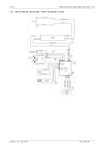
10.5


Electrical Scheme - Dental Light – Without Transformer Joystick 


Summary of Contents for ALYA

Page 1: ...ALYA INSTALLATION AND USER S MANUAL EN Edition 2 0 Sept 2018 Pag 1 di 32...

Page 2: ...3 3 HEADLIGHT INSTALLATION 19 3 3 1 Mechanical Requirements 19 3 3 2 Electrical Requirements 20 4 INSTRUCTION FOR USE 20 4 1 MOUNTING OF THE JOYSTICK LEVER 20 4 2 SWITCHING ON OFF AND ADJUST THE LIGHT...

Page 3: ...e paragraphs marked with this symbol contain instructions that must be carefully followed to avoid damaging the device harming the operator or the patient CAUTION These instructions warns you that you...

Page 4: ...ional qualification Understanding of language Those acquired for the professional qualification 1 3 3 Experience Those outlined to conduct the profession 1 3 4 Possible user handicaps For the use it i...

Page 5: ...ct or focus the light beam directly in the patient s eyes especially patients with greater risk of eye injury e g children with eye diseases diabetic patients older men In this case always use appropr...

Page 6: ...aximum period of 15 weeks if the following environmental conditions are met Environmental temperature from 20 C to 70 C Relative humidity from 10 to 90 Atmospheric pressure from 50 kPa to 106 kPa The...

Page 7: ...matically each time the light power supply is activated The remote cable allows the light commands to be duplicated by the dental unit Follow the instructions provided in the installation paragraph On...

Page 8: ...ction For the electrical connections comply with the instructions supplied in the installation paragraph 2 2 DESCRIPTION OF THE PARTS 1 Head light 2 Spring Arm central arm 3 Rear arm o trafo optional...

Page 9: ...3 digit Col Temperature e controllo riunito 4 digit Power supply and control 5 digit Available 6 digit Colors 7 8 9 digit Custom 3 1 5 Optical Group 5000 K 0 Joystick 17 24 V AC 22 33 V DC 0 0 White...

Page 10: ...tput 17 24 Vac Power 26 VA Rigidity 4000 V 2MOPP between primary and secundary Thermal protection In case of permanent application see note 1 Component built in part of a Medical Device Dental Unit Th...

Page 11: ...ectrical systems in premises for medical use In case of permanent application add following requirements The lamp must be installed with a multipolar device to separate it from the supply network meet...

Page 12: ...pply cable according to the specifications outlined in Tab 1 The applications are not supplied with the light Warnings for electrical danger and suspended masses The device has to be installed by spec...

Page 13: ...eiling 4 bores with 14 drill Fit the expanders 2 in these bores D Take the flange 1 Pass the power cable through the cable gland 5 then push the flange 1 against the ceiling do not choke the cable bet...

Page 14: ...w the assembling J Insert the ceiling light support 16 on the column 14 K Fit the column 14 in the special bore of the column fixing flange 7 L Lock the screw 13 and the two screws 18 with hexagonal s...

Page 15: ...14 and tighten Simultaneously pull the traction cord to push out the conductor of the lamp from the column fixing flange 7 of about 200 mm U Connect the lamp conductor to the terminal board 6 see ele...

Page 16: ...e always switched off Before starting the installation take care that the ceiling is suitable to bear the load of the application and dental light The anchor bolts provided with the application must b...

Page 17: ...e wire between the wall application 3 and the wall itself C Apply the three Caps 4 to the holes in the wall application 3 D Unscrew the screw 8 Remove the cover 7 insert the lamp in the ceiling applic...

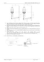
Page 18: ...in accordance with IEC EN 60601 1 by the installer A Once the fixing point has been established with reference a the center of the chair drill four holes diameter D14 in the floor in correspondence wi...

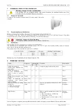
Page 19: ...in with adequate equipment The ring nut must be screwed in to give the correct rotational force to the head 3 Screw the safety screws F until the cut A into the brass nut is completely closed 4 take c...

Page 20: ...edition with one pole protected by appropriate fuse T1 25AL250V Minimum requirements Output 24 33 Vdc Power min 26 VA Dielectric strenght 4000 V 2 MOPP between primary and sec Continuous protection fr...

Page 21: ...lete light To adjust light intensity you need to stay still near the sensor until the desired intensity is obtained Adjustment enables passage from the maximum value to the minimum value again to the...

Page 22: ...follows 1 Press the Synchro button for 2 seconds then release it 2 On release a sound signal Beep will be heard and the blue LED on the Room Light lamp will go out to indicate that synchronization has...

Page 23: ...h in cotton wetted ethyl alcohol or the specific PERFLEX detergent Always squeeze the cloth to remove all the liquid in excess Water alcohol based disinfectants with 70 isopropyl alcohol or ethanol ar...

Page 24: ...however up to loss of the mechanical performance The parameters of the sterilisation cycle are as follows Cycle EN 13060 Temperature Pressure Holding Time Minimum B 121 C 207 kPa 15 min B 134 C 308 kP...

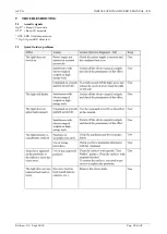
Page 25: ...TION AND USER S MANUAL EN Edition 2 0 Sept 2018 Pag 25 di 32 9 TROUBLESHOOTING 9 1 Acoustic signals OpL Beep 30 seconds OTP Beep 30 seconds OTP LED Overtemperature OpL Open LED detected 9 2 Quick Guid...

Page 26: ...nsformer not supplied in charge to installator T1 6AL 250V 24Vac T2AL 250V 24Vdc T1 25AL250V 17 24Vac T1 6AL 250V 22 33Vdc T1 25AL 250V Protection against electrical hazad Class II final classificatio...

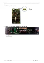
Page 27: ...ALYA INSTALLATION AND USER S MANUAL EN Edition 2 0 Sept 2018 Pag 27 di 32 10 1 ELECTRICAL DRAWINGS 10 2 Electronic Board in the Head 10 3 Electronic Board in the Rear Arm present only with Theia Tech...

Page 28: ...ALYA INSTALLATION AND USER S MANUAL EN Edition 2 0 Sept 2018 Pag 28 di 32 10 4 Electrical Scheme Dental Light with Transformer 230 V ac 240 V ac Joystick...

Page 29: ...ALYA INSTALLATION AND USER S MANUAL EN Edition 2 0 Sept 2018 Pag 29 di 32 10 5 Electrical Scheme Dental Light Without Transformer Joystick...

Page 30: ...ALYA INSTALLATION AND USER S MANUAL EN Edition 2 0 Sept 2018 Pag 30 di 32 10 6 Electrical Scheme Dental Light equipped with secondary light on rear arm Theia Tech...

Page 31: ...ALYA INSTALLATION AND USER S MANUAL EN Edition 2 0 Sept 2018 Pag 31 di 32 10 7 Electrical Scheme Dental Light only Head...

Page 32: ...ALYA INSTALLATION AND USER S MANUAL EN Edition 2 0 Sept 2018 Pag 32 di 32...

Reviews: