background image

Preparing the scanner hardware

• 

Ensure that the Power Block is completely charged. We recommend to have at least 2 fully-charged 
Power Blocks for scanning in extreme conditions.

• 

Set all scanning parameters prior to working with the scanner on-site. (E.g., scan project folders, file 
naming, user settings, etc.; scan resolution and quality, color settings, scan profile, detector settings, 
etc.) This will minimize the amount of time that the scanner will be exposed to the environment.

Setting up on-site and scanning operation in hot 
ambient conditions

This section provides details about how to set up the scanner with the cover.

Set up the tripod at the desired scan position following all recommendations in the scanner manual.

Insert a fully-charged power pack into the battery slot of the scanner. If a status indicator is present in the 
scanner, it should be removed while the scanner is switched off. Start the scanner and recall all desired scan 
/ project settings. After this step, the scanner should be in status 

Ready for measurement

. If a status 

indicator is inserted into the accessory bay, remove it before proceeding.

NOTE: 

We recommend you keep the scanner in moderate climate conditions during system start and 
parameter settings by the user (20 to 25 °C), for example in an air-conditioned car.

Mount the FARO® FOCUS Laser Scanner on the tripod and align the scanner's “Home” orientation if 
required. 

Installing the thermal protection cover

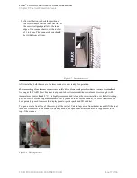
1. Take two covers out of the transport cooler.

2. Loosen the two Velcro straps at the bottom 

of the covers. Note that the covers are not 
identical, the display-side cover has an 
extra pad, shown in 

Figure 3-4


FARO

® 

FOCUS® Laser Scanner Accessories Manual

Chapter 3: Thermal Protection Covers

FARO FOCUS® LASER SCANNER (00.00)

Page 15 of 36

Summary of Contents for FOCUS Core

Page 1: ...FOCUS Laser Scanner Accessories Manual May 2021...

Page 2: ...BILITY TO FARO TECHNOLOGIES INC REGARDLESS OF THE FORM OF ACTION SHALL NOT EXCEED THE PURCHASE PRICE OF THE MATERIALS DESCRIBED HEREIN THE INFORMATION CONTAINED IN THIS MANUAL IS SUBJECT TO CHANGE WIT...

Page 3: ...ong with normal waste Take electronic products to recycling facilities that accept electronic devices Contact your local government or local waste disposal operators to comply with local laws FARO FOC...

Page 4: ...ng the thermal protection covers 14 Storing and transporting the thermal protective covers 14 Transporting the scanner to working site 14 Preparing the scanner hardware 15 Setting up on site and scann...

Page 5: ...he Scanner 25 Enabling the PanoCam in the Controller Software 26 PanoCam Calibration 27 PanoCam Scanning 29 Expediting the Scanning Process 29 PanoCam Example Images 30 Importing a PanoCam Project int...

Page 6: ...F Part numbers ACCSS8014 non display side of scanner ACCSS8049 display side of scanner PanoCam on page 21 Use the FARO PanoCam mount to attach a panoramic camera to the FOCUS LASER SCANNER The PanoCam...

Page 7: ...beyond a WARNING notice until the indicated conditions are fully understood and met CAUTION A CAUTION notice denotes a hazard It calls attention to an operating procedure or practice that if not corr...

Page 8: ...Page 8 of 36 FARO FOCUS LASER SCANNER 00 00 FARO FOCUS Laser Scanner Accessories Manual Chapter 1 Introduction...

Page 9: ...dicator NOTICE The status indicator is not waterproof Do not use the indicator in the rain or where water could drip onto it Inserting the status indicator The scanner should not be stored with the st...

Page 10: ...o the accessory bay on the left side of the scanner Forcing the status indicator into the black bay may damage either the status indicator the scanner or both The status indicator is now ready for use...

Page 11: ...2 Remove the status indicator by grasping it with two fingers on the corners shown in Figure 2 4 and pulling vertically Figure 2 4 Pull here to remove Figure 2 5 Do not pull here 3 Replace the access...

Page 12: ...Page 12 of 36 FARO FOCUS LASER SCANNER 00 00 FARO FOCUS Laser Scanner Accessories Manual Chapter 2 Status Indicator...

Page 13: ...scanner in temperatures between 40 C and 55 C 104 F to 131 F and in strong direct sunlight The covers provide shielding against IR radiation high performance thermal insulation to prevent excess heat...

Page 14: ...he scanning site the covers need to be kept cold optimum 15 C 5 F by transporting them in a high quality cooler equipped with ice packs or with active refrigeration Figure 3 2 Set of pre cooled therma...

Page 15: ...scanner If a status indicator is present in the scanner it should be removed while the scanner is switched off Start the scanner and recall all desired scan project settings After this step the scann...

Page 16: ...er side of the laser scanner housing Figure 3 5 Slide thermal protection cover onto scanner 4 Tighten and fix the two Velcro straps at the bottom of each cover so the cover fits tightly on the outer l...

Page 17: ...direct sunlight with temperatures greater than 40 C it is highly recommended to leave the cover installed over the full working period or series of scanning measurements But if you need to access the...

Page 18: ...in the preceding sections As a consequence repetitive scan operation under such conditions will be limited in time up to a point where the internal temperature control of the FARO Laser Scanner sends...

Page 19: ...and automation connection to the scanner Helical Adapter Upgrade Part number ACCSS8015 A bracket that prevents the scanner from rotating so that it can be used in helical mode Automation Test Box Part...

Page 20: ...Page 20 of 36 FARO FOCUS LASER SCANNER 00 00 FARO FOCUS Laser Scanner Accessories Manual Chapter 4 Automation Accessories...

Page 21: ...rmware 6 8 0 or newer l SCENE 2021 0 or later l Ricoh Theta Z1 camera l FARO PanoCam mounting bracket l 3mm Hex Key included PanoCam Mount Setup The first part of the hardware setup requires attaching...

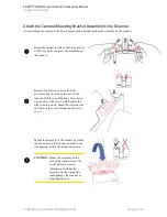
Page 22: ...crew which is located on the bottom of the mount CAUTION Do not over tighten the screw Damage to the camera or mount could result Proceed with attaching the camera mounting bracket assembly to the sca...

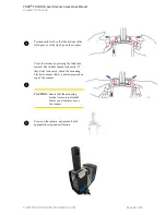
Page 23: ...ress down on one side of the cover which causes the other side to pop up Grasp the elevated side and remove the cover Retain the protective cover Mount the assembly to the scanner by fitting the conne...

Page 24: ...don t lock easily check the mounting bracket to ensure that it is placed properly on top of the scanner CAUTION Ensure that the mounting bracket is securely attached before you attempt to move the sca...

Page 25: ...about 45 degrees and then pull the assembly away from the scanner Use the hex key to loosen the camera screw Remove the camera being careful not to damage the USB C connectors Store the camera and mo...

Page 26: ...noCam in the Focus scanner GUI before you proceed with scanning To enable the PanoCam 1 From the Home screen tap the Parameters button 2 Tap Color Settings 3 Tap Panorama Camera FARO FOCUS Laser Scann...

Page 27: ...cessed in SCENE version 2021 0 or higher to determine all required system parameters for the camera with your user account A new full system calibration is required whenever you change computers or us...

Page 28: ...ot have proper color overlay repeat the system calibration and processing in Scene Repeat the calibration procedure in the following circumstances l If you are using a different camera or scanner othe...

Page 29: ...ish eye lenses are always clean and free of scratches Following are basic steps for performing a scan with the PanoCam mounting bracket and camera installed NOTE For detailed information about scannin...

Page 30: ...are and software meet the necessary requirements See PanoCam Requirements on page 21 PanoCam Example Images The following images represent example scan projects that include photos from the panoramic...

Page 31: ...nner operators l Ricoh Theta raw pictures l Projects To process a FOCUS project in SCENE 1 Remove the SD card from the scanner and insert it into your computer SCENE recognizes the card and prompts yo...

Page 32: ...enter The area is included in the point cloud but not captured in the PanoCam picture and as a result not colorized in the point cloud Occlusions occur due to parallax issues similar to how your left...

Page 33: ...olor information caused by the occlusion The best way to reduce or eliminate occlusions entirely is to capture a greater number of scans in areas with complex structural detail Occlusion Examples Foll...

Page 34: ...In the above example the area behind the pipe is the occluded area FARO FOCUS Laser Scanner Accessories Manual Chapter 5 PanoCam FARO FOCUS LASER SCANNER 00 00 Page 34 of 36...

Page 35: ...point cloud areas Moving objects during scanning and color capture can also lead to incorrectly colored point cloud areas Activated filters like contour or edge artifact filters limit point cloud colo...

Page 36: ...com FARO Singapore Pte Ltd No 03 Changi South Street 2 01 01 Xilin Districentre Building B SINGAPORE 486548 TEL 65 6511 1350 Email supportap faro com FARO Japan c 716 Kumada Nagakute City Aichi 480 1...

Reviews: