Model ULC Series
06012021ULC,Rev i
Page 11 of 54
b. To allow for movement of the equipment during servicing, we recommend using
½” industrial grade flexible hose; 8’ (2.5m) in length.
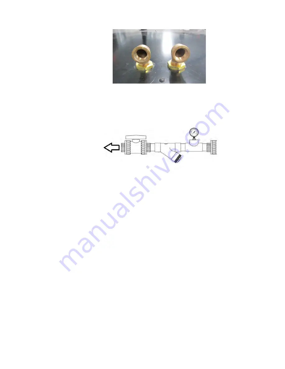
c. We strongly recommend installing a 1/2” ball valve at the water inlet along with a
strainer and pressure gauge. These will facilitate any servicing or testing
requirements.
d. Check all connections for leaks.
e. Verify the water differential pressure is adequate along with nominal flow and
temperature requirements (see Specifications).
5.0 Control System
The unit consists of heating, cooling components, fans, and control components. The major cooling
components include a compressor (heat moving component), condenser (heat rejection part),
evaporator (heat absorption part) and PWM valve (refrigerant flow control devices). Controls consists
of a circulation fan, IDEC PLC Series FC6A, RTD temperature sensors, PWM valve hot gas control,
solid state relay and miscellaneous other hardware.
There are various settings that the user can adjust to suit their specific requirements. These are
described in the Operation section of this manual.
6.0 Operation
1. POWER CONTROL:
Electrical power is provided via a power cord. Internally, power passes through a 2-pole
main circuit breaker, which is accessible inside the main control enclosure.
The only user accessible means of power disconnection is by unplugging the power cord
from the wall receptacle.
To
refrigeration
system
water
connections


