III. ENGINE REPAIR
46
7. Connecting rod
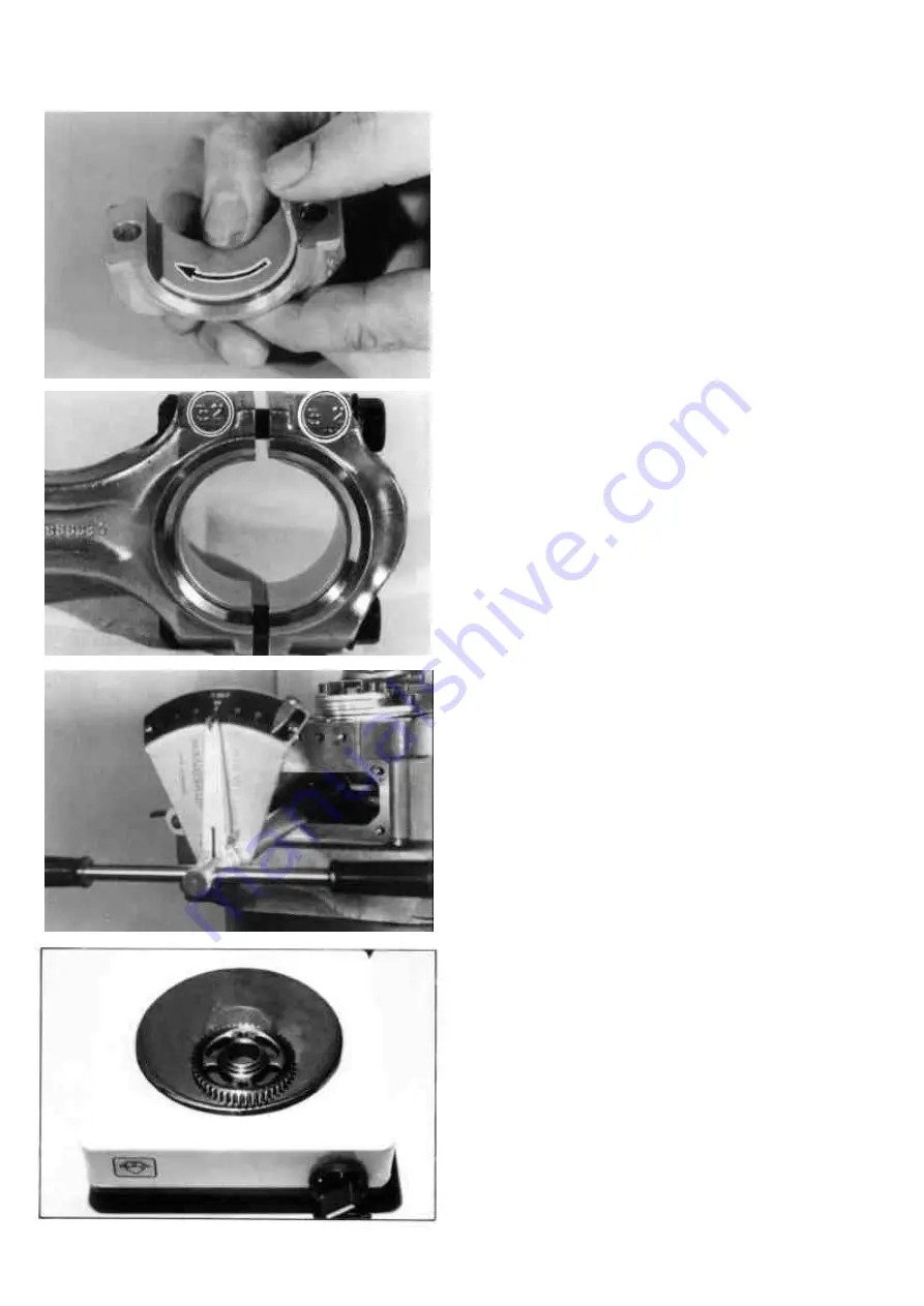
To install new bearing shells, take a
shell half and lay it to approx. ¾ into the
cap. Now press with your thumb the
bearing in a sliding movement onto ist
seat. The bearing lip must fit into the
grove in the cap. The connection rod
side shell half is installed the same way.
(Figure 10)
Notice the numbers stamped onto one
side of the conrod. These are matching
marks i.e. identical numbers must be on
rod and cap.
(Figure 11)
Oil the bearing shells and install conrod
into the crankcase until it seats on the
crank pin. Insert the conrod cap through
the inspection cover.
Attention: The stamped numbers
must be aligned on the same side of
the rod but it is not important which
engine side the numbers face.
Tighten the conrod nuts to the
specified torque and reinstall the
crankcase cover.
(Figure 12)
8. Camshaft
Heat the camshaft gear wheel in an oil
bath or an electric heater plate to 90-
100°C (195-210°F). Thrust gear down
onto the camshaft using a suitable
length of pipe and a hydraulic press.
Attention: The chisel mark for the
timing must face towards cam side of
assembly.
(Figure 13)
Summary of Contents for 15D Series
Page 8: ...III 1 DISASSEMBLY 10...
Page 9: ...II TECHNICAL DATA 11...
Page 15: ......
Page 27: ...III ENGINE REPAIR 28 III 2 DIMENSION TABLE WEARING PARTS...
Page 28: ...III ENGINE REPAIR 29...
Page 29: ...III ENGINE REPAIR 30...
Page 30: ...III ENGINE REPAIR 31...
Page 31: ...III ENGINE REPAIR 32...
Page 32: ...III ENGINE REPAIR 33...
Page 33: ...III ENGINE REPAIR 34...
Page 34: ...III ENGINE REPAIR 35...
Page 35: ...III ENGINE REPAIR 36...
Page 36: ...III ENGINE REPAIR 37...
Page 37: ...III ENGINE REPAIR 38...
Page 38: ...III ENGINE REPAIR 39...
Page 39: ...III ENGINE REPAIR 40...
Page 40: ...III ENGINE REPAIR 41...
Page 41: ...III ENGINE REPAIR 42 III 3 ENGINE REASSEMBLY...
Page 73: ...74...
Page 74: ...75...
Page 75: ...76...
Page 76: ...77...


