III. ENGINE REPAIR
52
- Install the cover. Align the camshaft
gear and gear cover timing marks. Now
check the flywheel and crankcase timing
marks. The timing is acceptable, if they
are within
±
2 mm (
±
0.0787) of each
other.
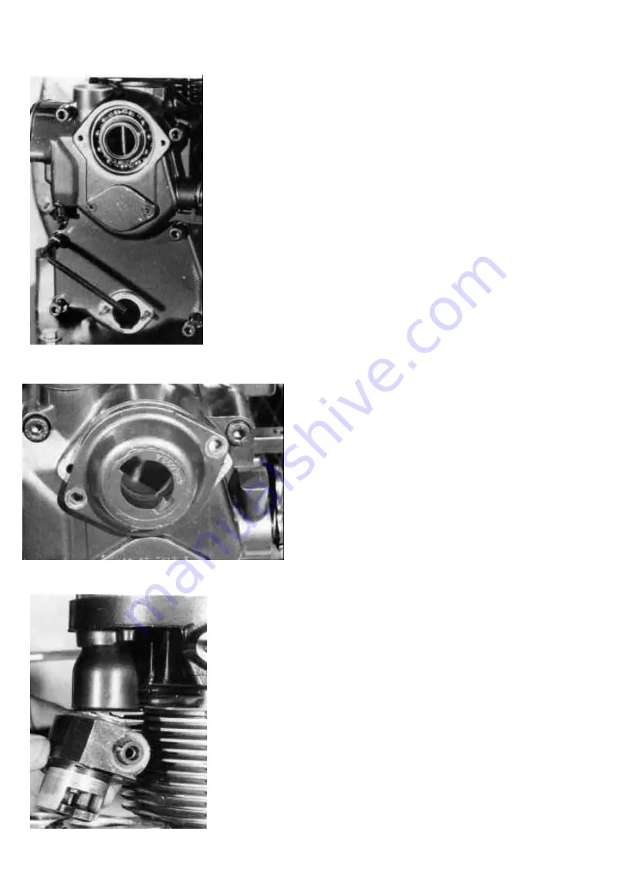
When installing the gear cover screws,
note that the top two and bottom left
screw are longer than the other three.
(Figure 28)
Place new o-ring in the flute of the
support starting handle. Lubricate the
camshaft and the sealing lips of the oil
sealing ring. Do not push the guide
straight onto the gear cover. Instead use
a light twisting motion until the guide
seats itself. Tighten the two guide
screws to the specified torque.
(Figure 29)
13. Compression release device
Slide the protection tube up into its hole
in the cylinder head as far as possible.
Remember to install a new o-ring in the
cylinder head. Assemble the
decompression device with new o-ring
and gasket.
Attention: Before reinstal-ling the
decompression device check if
retaining pin for the shaft (arrow) is
still in place.
(Figure 30)
Summary of Contents for 15D Series
Page 8: ...III 1 DISASSEMBLY 10...
Page 9: ...II TECHNICAL DATA 11...
Page 15: ......
Page 27: ...III ENGINE REPAIR 28 III 2 DIMENSION TABLE WEARING PARTS...
Page 28: ...III ENGINE REPAIR 29...
Page 29: ...III ENGINE REPAIR 30...
Page 30: ...III ENGINE REPAIR 31...
Page 31: ...III ENGINE REPAIR 32...
Page 32: ...III ENGINE REPAIR 33...
Page 33: ...III ENGINE REPAIR 34...
Page 34: ...III ENGINE REPAIR 35...
Page 35: ...III ENGINE REPAIR 36...
Page 36: ...III ENGINE REPAIR 37...
Page 37: ...III ENGINE REPAIR 38...
Page 38: ...III ENGINE REPAIR 39...
Page 39: ...III ENGINE REPAIR 40...
Page 40: ...III ENGINE REPAIR 41...
Page 41: ...III ENGINE REPAIR 42 III 3 ENGINE REASSEMBLY...
Page 73: ...74...
Page 74: ...75...
Page 75: ...76...
Page 76: ...77...


