background image

Fasep 2000 srl

Rev. 1.8

Balatron 222/212: User’s Manual

23 January 2020

5-1

5

MEASUREMENT AND CORRECTION OF UNBALANCE

5.1

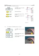
Placing the wheel rim on the wheel balancer

5.1.1

Select the cone or flange suitable for the wheel to be balanced. Specific mounting instructions are delivered with each
flange.

NOTE

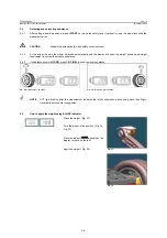
The operation of centering and tightening of the wheel on the flanges is of basic importance for correct

balancing. Good results depend on proper performance of these procedures.
Clean accurately all cones, shaft and adapter surface before placing the wheel on the wheel balancer.

!

CAUTION

Always make sure flanges are correctly locked on the motor shaft and wheel is correctly locked on
the flange being used. 

5.2

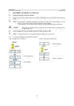
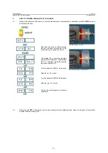
How to compensate unbalance of flanges using AFC function (optional for B212)

NOTE

This operation allows to put compensate unbalance of flange and other accessories.

5.2.1

Lock the required flange on the shaft without the wheel.

HOW TO TURN ON AFC FUNCTION 

             HOW TO TURN OFF AFC FUNCTION

The AFC led blinking.

The AFC led is on.

Remove the flange.

The AFC led switch off.

Summary of Contents for B222

Page 1: ...www fasep it User s MANUAL B222 B212 B112...

Page 2: ...12 User s Manual 23 January 2020 For any information please contact www fasep it e mail vendite fasep it FASEP 2000 srl Via Faentina 96 50032 Ronta Fi Italy Tel 39 055 8403126 Fax 39 055 2691906 i B22...

Page 3: ...ience breakdown accidents due to unauthorized modifications of the unit use of non original or unauthorized accessories see Accessories listing in this manual for a list of original accessories availa...

Page 4: ...of Wheel Balancer USER 4 2 4 3 ALU SE calibration USER 4 3 5 MEASUREMENT AND CORRECTION OF UNBALANCE 5 1 5 1 Placing the wheel rim on the wheel balancer 5 1 5 2 How to compensate unbalance of flanges...

Page 5: ...price of the unit and must be purchased separately This unit is designed for indoor use only see Environmental Data appendix for reference CAUTION This unit is designed to spin vehicle wheels only wit...

Page 6: ...ical hookup is to be provided by a qualified electrician 2 4 2 A fusible wall mounted switchbox is required at the installation site This switch should provide on off control and overload protection f...

Page 7: ...ecial Functions MODE To select balancing type Dynamic Static Alu SET Confirm selection 9 OPER To select Operator 1 or Operator 2 10 FINE To select reading scale 11 FUNC To select specific functions ST...

Page 8: ...weight readings c indicated point of unbalance constantly wrong d more than 2 spins required to balance wheels repeatedly Switch on the wheel balancer Press SET when SOF X XX software version is displ...

Page 9: ...Put the calibration weight Fig 14 Press 10 FINE to see actual values 160 0 3 is correct result When all LED left side are lit calibration weight must be at exactly 6 o clock If no press 11 FUNC to ca...

Page 10: ...software version is displayed ATTENTION select mode CAL USR Put the rod in 0 position Fig 17 Put the rod in internal side of flange Fig 18 Put the rod in the internal side of the rim Fig 19 Select the...

Page 11: ...on proper performance of these procedures Clean accurately all cones shaft and adapter surface before placing the wheel on the wheel balancer CAUTION Always make sure flanges are correctly locked on t...

Page 12: ...alancer can be used by 2 operators in the same time Everyone can memorizes the dimensions of the wheel to balance with 9 OPER button The machine memorizes the operating procedure too 5 3 1 DYNAMIC MOD...

Page 13: ...ODE to select the operating mode Fig 23 Fig 24 Select the wheel diameter Insert the internal measure IN 1 Fig 24 Fig 26 Insert the external measure IN 2 Fig 26 Fig 32 5 3 4 ALU S 1 MODE ALU S 2 MODE A...

Page 14: ...4 2 At the end of the spin the wheel will brake automatically and the display will show the weight position and weight requirement to correct the wheel s unbalance 5 4 3 If unbalance shown is GOOD pr...

Page 15: ...er mounting the tyre the wheel must be put on the shaft in the same position as before Left display 20 in example indicates present static unbalance Right display 55 in example indicates possible redu...

Page 16: ...balance is calculated press 11 FUNC to enter split function Turn the wheel until POS 1 is displayed Mark the tyre when the first spoke selected is at 12 o clock Turn the wheel until POS 2 is displayed...

Page 17: ...a good result c11 0s Percent of wheels with diameter 11 from 11 to 17 Percent of wheels with the indicated diameter 17 0s Percent of wheels with diameter 17 CAL Number of calibrations pne Number of P...

Page 18: ...25 to 70 C Relative humidity 5 at 95 to40 C Safety Features 1 The Balance Weights Holder may be removed for servicing It is secured to the machine body through screws so that only voluntarily it may b...

Page 19: ...electrical and mechanical parts should be done only by an Authorized FASEP 2000 Service Center C Errors and Malfunctions recognized by the Computer Errors may apply to some model only ERR 1 Shaft doe...

Page 20: ......
Page 21: ...ulations Direttiva macchine Directive Machines Supply of Machinery Safety Regulations 2008 Bassa Tensione Low Voltage Directive Electrical Equipment Safety Regulations 2016 Compatibilit Elettromagneti...

Page 22: ...wymienione urzadzeine jest zgodne z nasepujacymi normami I dyrektywmi Tipo di prodotto Type of equipment Typ urzadzenia equilibratrici wheel balancers wywazarka do kol Modello Nr di serie Model Serial...

Reviews:

Related manuals for B222