background image

6  

User’s manual

INTRODUCTION

The purpose of this manual is to furnish the owner and operator with a set of practical, safe instruc-

tions on the use and maintenance of the TECO tyre changer.

Follow all the instructions carefully and the machine will give you the efficient and long-lasting service 

that has always characterized TECO  products, making your work considerably easier.

The following points define the levels of danger regarding the machine, associated with the warning 

captions found in this manual:

DANGER

Refers to immediate danger with the risk of serious injury or even death.

WARNING

Dangers or unsafe procedures that can cause serious injury or even death.

CAUTION

Dangers or unsafe procedures that can cause minor injuries or damage to property.

Read these instructions carefully before powering up the machine. Keep this manual and all illustrative 

material supplied with the machine in a folder near the tyre changer where it is readily accessible for 

consultation by the machine operators.

The technical documentation supplied is considered an integral part of the machine; and must always 

accompany the equipment if it is sold or transferred to a new owner.

The manual is only to be considered valid for the model with the serial number indicated on the 

nameplate applied to it.

  WARNING

Observe the contents of this manual: the producer declines all liability in the case of uses of 

the machine not specifically described and authorized in this manual.

  WARNING

This machine must be used only by qualified and authorized personnel. A qualified operator 

is construed as a person who has read and understood the tyre changer manufacturer’s 

instructions as well as the tyres and wheel rims manufacturers’, is suitably trained, and is 

conversant with safety and adjustment procedures to be adhered to during operations. Use 

of the machine by unskilled staff may constitute a serious risk for the operator and for the 

final user of the product processed (the wheel rim and tyre assembly).

NB: 

Some of the illustrations in this manual have been taken from photographs of prototypes: standard 

production machines may vary in some respects.

These instructions are intended for people with basic mechanical skills. We have therefore omitted 

detailed descriptions of procedures such as how to loosen or tighten the fixing devices on the ma-

chine. Do not attempt to perform operations unless properly qualified and with suitable experience. 

In case of need, contact an authorized Service Centre for assistance.

Summary of Contents for RAE.2108

Page 1: ...0 Tel 39 055 8403126 E mail info fasep it Fax 39 055 8403354 WWW www fasep it FASEP 2000 srl Via Faentina 96 50030 Ronta Fi Italy Sistema Qualit Certificato ISO 9001 2000 l i a m E 6 2 1 3 0 4 8 5 5 0...

Page 2: ...productionetd adaptationtotaleoupartielleparn importe quel moyen y compris microfilms et copies photostatiques sont r serv s Les informations contenues dans ce manuel sont sujettes des variations sans...

Page 3: ...stimmung EN ISO IEC 17050 1 Egzemplarz niniejszej deklaracji jest zgodny z dyretyw EN ISO IEC 17050 1 Il firmatario della presente dichiarazione la persona autorizzata a costituire il fascicolo tecnic...

Page 4: ......

Page 5: ...R S LABEL 12 TECHNICAL DATA 13 STANDARD ACCESSORIES 14 ACCESSORIES SUPPLIED ON DEMAND 14 SPECIFIED CONDITIONS OF USE 14 MAIN OPERATING PARTS 15 WARNING SIGNALS 17 PRACTICAL HINTS 18 USE 19 DEMONTAGE 2...

Page 6: ...to a new owner The manual is only to be considered valid for the model with the serial number indicated on the nameplate applied to it WARNING Observe the contents of this manual the producer decline...

Page 7: ...age Temperature 25 55 C WARNING Do not stack other goods on top of the packing to avoid damaging it Handling To move the packing insert the tines of a fork lift truck into the slots on the base of the...

Page 8: ...that rod P of the tower tilt cylinder is inserted in the U bolt Q Insert pin R and fasten it with self locking nut S without tightening it to the bottom Fasten the tower on the machine s body with the...

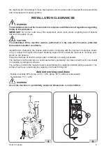
Page 9: ...the chosen work position complying with the minimum clearances shown in fig 3 adjust the height of the bead breaking support foot so that the machine is correctly posi tioned on the flooring Place th...

Page 10: ...al wiring diagram in this manual In order to prevent the machine from being used by unauthorized personnel it is advisable to disconnect the power supply plug when the machine remains idle switched of...

Page 11: ...ctly and that they are adequately supervised Never leave nuts bolts tools or any other equipment on the tyre changer as they may become entrapped between moving parts Not touch power lines or the insi...

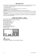
Page 12: ...street wheels The machine is solidly constructed It operates with the wheel in a vertical position for bead breaking and horizontal for mounting and demounting tyres All machine movements are controll...

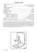
Page 13: ...electronic components 11 5 kg Noise level A weighted sound pressure level LpA at the working position 70 dB A 3dB A The noise levels indicated correspond to emission levels and do not necessarily rep...

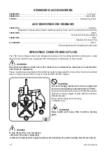
Page 14: ...WARNING Any other operation carried out on the machine is considered as improper use and shall be construed as negligence These machines are equipped with an inflation system independent from any oth...

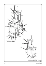
Page 15: ...machine main operating parts are shown in fig 9 1 Reverse control pedal 2 Turntable 3 Bead breaker pedal 4 Bead breaker arm 5 Clamp control pedal 6 Clamp 7 Vertical arm 8 Horizontal arm 9 Vertical po...

Page 16: ...16 User s manual 9 standard version t i version tubeless inflating 13 14 11 22 12 10 16 6 2 7 4 17 3 5 1 8 15 21 19 20 23 9...

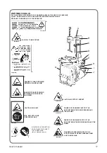
Page 17: ...OF HAND CRUSHING BETWEEN MOUNTING HEAD AND WHEEL D CAUTION AIR BLAST MAX AIR SUPPLY LINE PRESSURE 16 BAR E INFLATING GUN CONNECTION DO NOT DIRECTLY CONNECT THE COMPRESSOR only on standard version CAUT...

Page 18: ...im wheels some wheels have alloy rims where the drop centre A is very small or non existent fig 10 B These rims are not approved by the DOT Department of Transportation standards these initials certif...

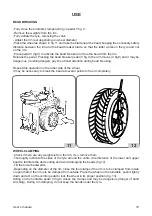
Page 19: ...eaking Repeat this operation on the other side of the wheel It may be necessary to break the bead at several points to free it completely WHEEL CLAMPING Check if there are any weights left on the rim...

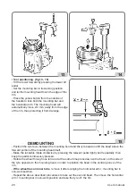
Page 20: ...tyre bead and lift the bead above the forward portion of the mounting head itself Make the turntable rotate clockwise by pressing the relevant pedal lightly and repeatedly then keep the pedal continuo...

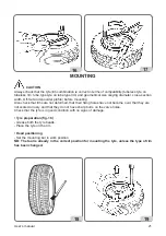
Page 21: ...eck that rims are not deformed that their fixing holes have not become oval that they are not scaled or rusty and that they do not have sharp burrs on the valve holes Check that the tyre is in good co...

Page 22: ...t be carried out in accordance with the instructions below Safety goggles with plain lenses and safety footwear must be worn CAUTION During this operation noise levels assessed at 85 dB A may occur Op...

Page 23: ...or a short period to the bead seating position fig 20 The tyre will expand and the beads will seat Continue to press the pedal in the inflation position fig 21 until the beads are completely sealed No...

Page 24: ...disconnected from the air supply system the devices marked with the warning sign shown above may remain pressurised The filter regulator lubricator is equipped with a semiautomatic condensation drain...

Page 25: ...L INFORMATION The following disposal procedure shall be exclusively applied to the machines having the crossed out bin symbol on their data plate This product may contain substances that can be hazard...

Page 26: ...g of the product and properly dispose of dead batteries if contained in the product With your help the amount of natural resources used to produce electrical and electronic equipment can be reduced th...

Page 27: ...ns of each type of extinguisher GLOSSARY Air delivery regulator Union allowing regulation of the air flow Beading Operation which takes place during inflation and ensures perfect centring between the...

Page 28: ...ylinder lacks force fails to break beads and leaks air Silencer plugged Renew silencer Cylinder seals worn Renew seals Renew bead breaker cylinder Bead breaker cylinder leaks air around the rod Air ga...

Page 29: ...es not authorize users to carry out work on the machine with the exception of those operations expressly described in the user manual It only enables users to provide the technical assistance service...

Page 30: ...11 12 x 9 10 x 7 8 x 5 6 x 3 4 x 1 2 L 0 R 1 2 3 L1 ELEMENTI Elements CONTATTI Contacts W2 U1 U2 V2 V1 W1 W2 U1 U2 V2 V1 W1 200 220 240V 380 415 440V MORSETTIERA Junction Box F F F Power Phase 400V 3...

Page 31: ...ARITA Reverse Polarity Switch x 11 12 x 9 10 x 7 8 x 5 6 x 3 4 x 1 2 L 0 R 1 2 3 ELEMENTI Elements CONTATTI Contacts F F Power Phase Neutral 230V 1 50 Hz 250V 16A 250V 16A 240V 1 50 Hz 250V 16A 250V 1...

Page 32: ...TATTI Contacts 1 3 5 7 9 11 2 4 6 8 10 12 13 15 17 19 21 23 14 16 18 20 22 24 L2 23 24 x x x 21 22 x 19 20 x 17 18 x x 15 16 x x 13 14 x 11 12 x 9 10 x 7 8 x x 5 6 x x 3 4 x 1 2 L2 L1 0 R 1 2 3 4 5 6...

Page 33: ...ER 11 VALVOLA DI GONFIAGGIO INFLATING VALVE 12 VALVOLA A MEMBRANA VALVE 13 VALVOLA DI SICUREZZA SAFETY VALVE 14 UNITA DI GONFIAGGIO INFLATE UNION BOX 15 SILENZIATORI REGOLABILI REGULATE SYLENCER 16 VA...

Page 34: ......

Page 35: ......

Page 36: ......

Reviews: