ELECTRICAL AND PNEUMATIC CONNECTIONS
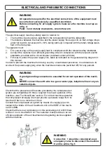
WARNING
All operations required for the electrical connections of the equipment must
be carried out exclusively by a qualified electrician.
Before connecting for air supply system, make sure the machine is set up as
in fig. 4:
Pedal 3 and 4 totally downwards, column forward.
The electrical supply must be suitably sized in relation to:
1.
The machine input power as specified in the corresponding machine data plate;
2.
The distance between the machine and the power supply hook-up point, so that voltage drops
under full load do not exceed 4% (10% during start-up) compared with the rated voltage speci-
fied on the data plate.
The operator must:
1.
Fit a power plug on the power supply lead in compliance with the relevant safety standards
2.
Connect the machine to an efficient grounding circuit in compliance with the relevant electric
standards, provided with a circuit breaker (residual current at 30mA)
3.
Fit fuses to protect the power supply line, rated as indicated on the general wiring diagram in
this manual.
In order to prevent the machine from being used by unauthorized personnel, it is advisable to di-
sconnect the power supply plug when the machine remains idle (switched off) for long periods.
WARNING
A good grounding connection is essential for correct operation of the machi-
ne.
NEVER connect the earth wire to a gas or water pipe, telephone line or any un-
suitable objects.
7
Check that the pressure and flow-rate provided by the compressed air
system are compatible with those required for proper operation of the
machine
—see “Technical Data” section. For correct machine operation
the compressed air supply line must provide a pressure range from no
less than 8 bar to no more than 16 bar.
Connect the compressed air system by means of a supply pipe con-
nected to the intake of the air treatment unit on the SIDE of the machi-
ne COLUMN.
Check that there is air lubrication oil in the lubricating unit; refill if there
is little or no oil. Use SAE20 oil. The customer must provide an air cut-
off valve upstream of the air treatment and regulating device supplied
with the machine. .
WARNING
Connection 1 should be considered as an
emergency valve to disconnect the machine
from the airline fig.5
5
4
Summary of Contents for RASE.TOP.2248
Page 13: ...DECALCOMANIE 13 9 10 1 2 3 4 9 23 8 5 6 10 11 12 13 18 14 15 16 17 17 19 20 21 22 7...
Page 38: ...LABELS 13 9 10 1 2 3 4 9 23 8 5 6 10 11 12 13 18 14 15 16 17 17 19 20 21 22 7...
Page 52: ...SCHEMA ELETTRICO ELECTRIC SCHEME 27 S 40 2 P...
Page 53: ...28 SCHEMA ELETTRICO ELECTRIC SCHEME S 40 2 P...
Page 54: ...SCHEMA ELETTRICO ELECTRIC SCHEME S 40 2 E 29...

