20
Always remember that the stronger is the tyre’s adherence to rim, the slower must be the disk’s
penetration.
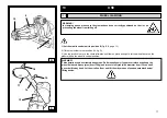
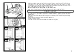
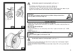
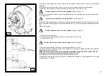
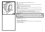
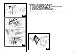
7) Use the joystick (2, fig. C, page 9) to move the tool arm to rest position, move it up and turn the tool by
means of the proper knob. Move the tool arm to the left of the wheel to be demounted, lower it and move it
to work position (fig. G)
ATTENTION!
Do not keep your hands on the tool when moving it to work position, because they could
get trapped between tool and wheel.
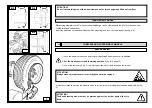
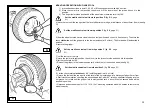
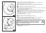
5) Let the wheel rotate and, at the same time, let the bead breaking disk move forward, with a stick-slip
motion, following the rim profile as well as possible.
6) Go on until the first bead is fully detached.
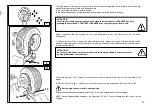
To facilitate this operation, grease tyre bead and rim edge while the wheel is rotating.
ATTENTION!
To avoid any risk when greasing the beads, make the wheel rotate CLOCKWISE if you are
greasing the outer bead, COUNTERCLOCKWISE if you are greasing the inner bead.
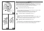
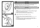
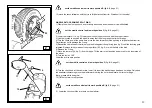
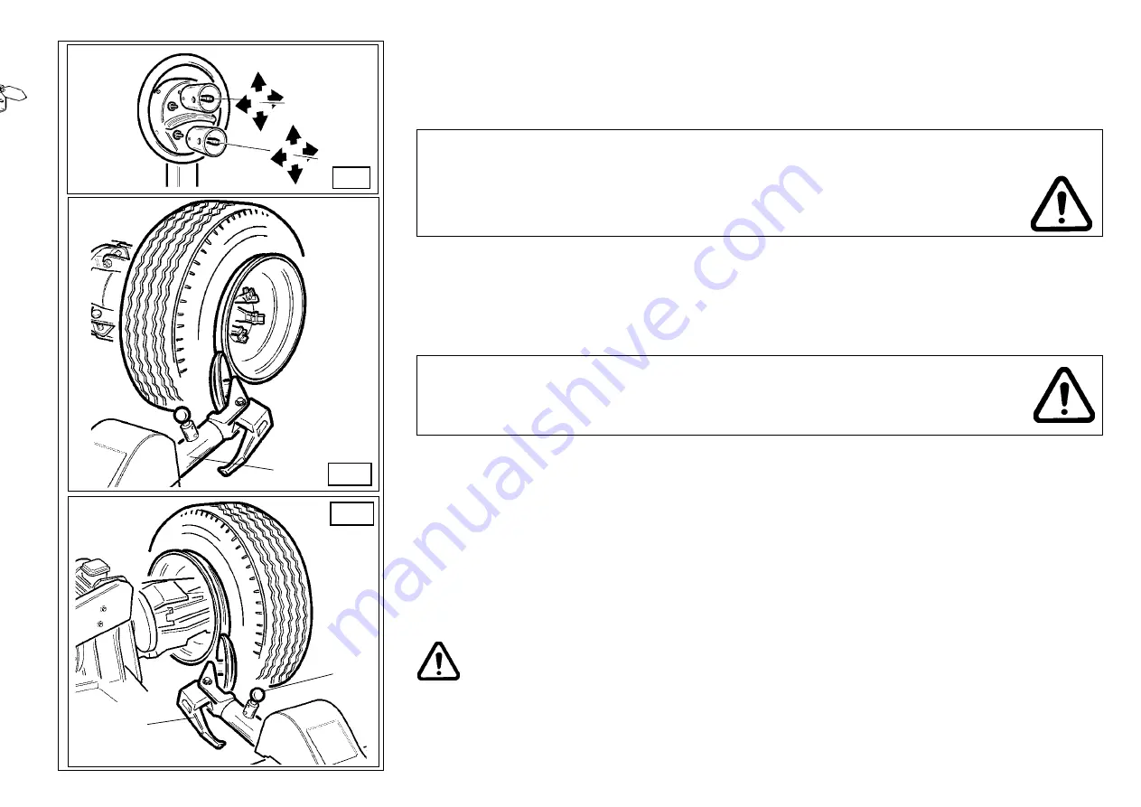
8) Use the joystick (1, fig. C, page 9) to move chuck and tool arm until this one is in the inner side of the
wheel.
9) Use the joystick (2, fig. C, page 9) to move the arm back to work position and turn the tools by 180°
Set the mobile control unit in work position
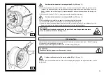
Repeat the operations described by point 5) and 6) until the second bead is fully detached.
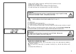
NOTE: during bead breaking operation, the finger tool (18, fig. G) can be lowered so that it won’t be an
obstacle.
C
1
2
F
14
G
19
18


