23
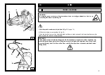
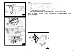
Set the mobile control unit in work position C
(fig. B/8)
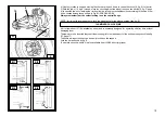
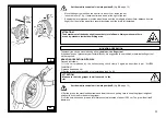
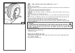
6) Set the disk against the second bead and turn the chuck until the gripper is in the lowest position (at 6
o’clock)
7) move the disk away from the wheel
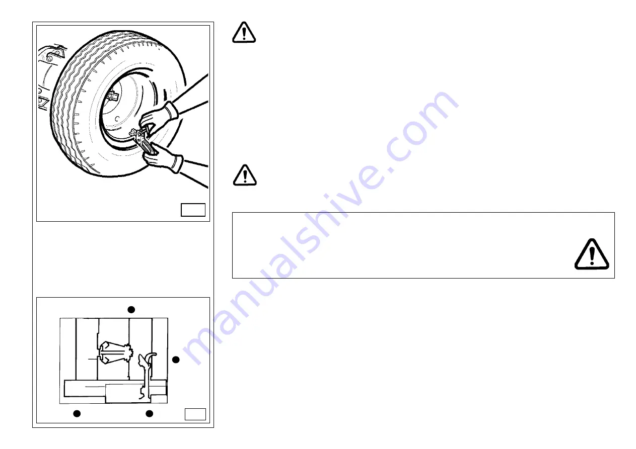
8) remove the gripper and reinstall it again in the lowest position (at 6 o’clock) but out of the second bead
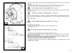
(see. Fig. N)
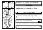
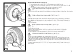
9) turn the chuck clockwise by 90° to bring the gripper to 9 o’clock.
10) Move the disk inwards of about 1-2cm. from the rim edge, taking care to let it at about 5mm. from the
profile. Start clockwise rotation checking the second bead that, after 90° rotation, shall start slipping into the
rim groove.
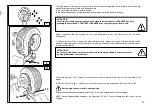
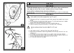
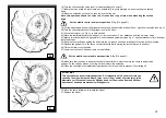
11) at the end of mounting phase, move the tool away from the wheel, tilt it to rest position and remove the
gripper
12) lower the chuck until the wheel rests on the machine baseframe.
Set the mobile control unit in work position C
(fig. B/8)
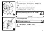
13) close the chuck jaws completely, taking care to hold the wheel to prevent it from falling off.
ATTENTION!!
This operation can be extremely dangerous. Do it manually only if you are certain you can
keep the wheel balanced. Heavy tyres (over 110kg) and/or oversize tyres (with diameter over
130cm) shall never be lifted by hand. Let them roll on floor and lift them by means of an
adequate mechanical lifting device.
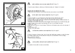
14) Move the chuck as to release the wheel
15) Move the wheel away.
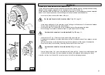
NOTE: according to the tyre you are operating on, you can decide to speed up the a.m. operation,
mounting both beads at the same time:
-
proceed as described in point 1,2,3,4 above, but instead of fixing the gripper to only one bead (see point
4), fix it to both.
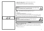
- Lift the rim with the hooked tyre on it and turn it counterclockwise of about 15-20 cm. (gripper at 10
o’clock)
- Proceed as described from point 10 to 15 above.
C
D
B
A
B/8
N


