INSTRUCTION, USE
AND MAINTENANCE MANUAL
GB
Page 19 of 168
7522-M001-14_P
GG40256.11SL - GG40256.11ST - GG40256.15
GG40256T.15 - GG40256A.15 - GG40256D.15
GG40256TD.15 - GG40256.15SL - GG60360.15
GG60360T.15 - GG60360A.15 - GG60360D.15 - GG60360TD.15
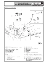
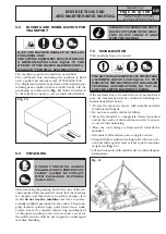
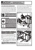
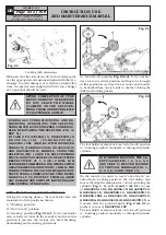
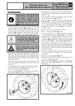
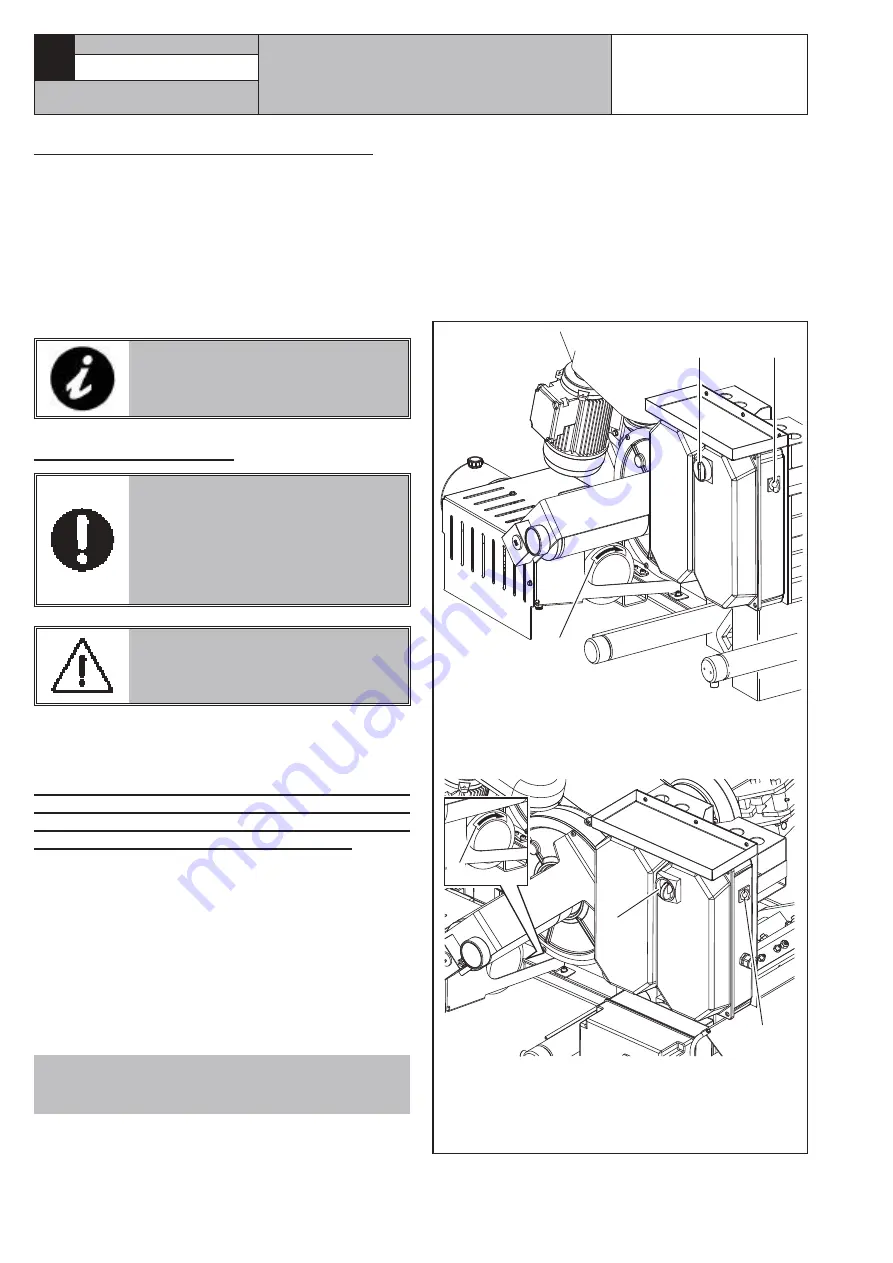
10.2 Check of motor rotation direction
Once the last electrical connection has been termina-
ted, power the machine with the main switch. Make
sure the motor of the hydraulic power unit rotates in
the direction indicated by the arrow (
Fig. 14 ref. B
)
visible on the electric motor cap. If rotation should
occur in the opposite direction, the machine must be
immediately stopped and phase inversion must be
executed inside the plug connection in order to reset
the correct rotation direction.
FAILURE TO OBSERVE THE ABO-
VE INSTRUCTIONS WILL IMME-
DIATELY INVALIDATE THE WAR-
RANTY.
10.3 Electrical checks
BEFORE STARTING UP THE TYRE-
CHANGER, BE SURE TO BECOME
FAMILIAR WITH THE LOCATION
AND OPERATION OF ALL CON-
TROLS AND CHECK THEIR PRO-
PER OPERATION (SEE PAR. “CON-
TROLS”).
CARRY OUT A DAILY CHECK OF
MAINTAINED-TYPE CONTROLS
CORRECT FUNCTIONING, BEFORE
STARTING MACHINE OPERATION.
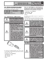
Once the plug/socket connection has been made, turn
on the machine using the master switch (
Fig. 14
ref. A
).
O n l y f o r VA R G N AV B T H ( G G 4 0 2 5 6 . 1 5 -
GG40256T.15 - GG60360.15 - GG60360T.15) and
VARGNAVDBTH (GG40256D.15 - GG40256TD.15 -
GG60360D.15 - GG60360TD.15) versions
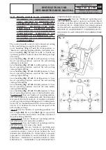
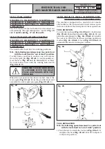
Then horizontally or vertically move the lever (
Fig. 16
ref. H
): the red LED (
Fig. 16 ref. B
) will turn on.
Wait a few seconds for the green LED turning on
(
Fig. 16 ref. A
) and then release the lever (
Fig. 16
ref. H
).
In the end, the green LED (
Fig. 16 ref. A
) flashes to
indicate that the machine is ready for operation.
N.B.: when a control is operated, the green LED
(Fig. 16 ref. A) light is fixed: it flashes again
when it is released.
ONCE THE ASSEMBLY OPERATIONS HAVE
BEEN ENDED, CHECK ALL MACHINE FUN-
CTIONS.
If during the operations the red LED (
Fig. 16 ref. A
)
turns on and the green led turns off, charge the control
batteries with the provided socket for battery charger,
located under the control (
Fig. 16 ref. M
).
The machine is equipped with a device for the interrup-
tion of the communication between the control and the
electrical panel, when more than 6 hours have passed
after the last executed control. In this case, just repeat
the turning on operations described in the “Electrical
checks” chapter.
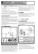
A
C1
B
B
A
C2
Fig. 14
KEY
A – Main switch
B – Rotation direction of power unit motor
C1 – Selector 1-0-2 for self-centring chuck speed control
C2 – Selector 1-2-3 for self-centring chuck speed control
Only for GG40256D.15, GG40256TD.15,
GG40256.11SL (VARGNAV43AD), GG40256.15SL
(model with inverter version) (VARGNAV43AD)
GG60360D.15 and GG60360TD.15 versions

