INSTRUCTION, USE
AND MAINTENANCE MANUAL
GB
Page 27 of 168
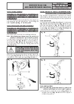
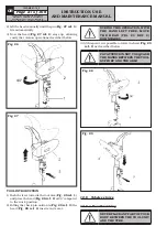
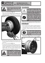
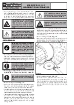
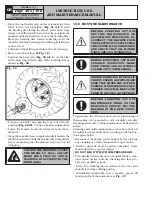
2) Lift the head manually until the pin (
Fig. 27 ref. 3
)
fits automatically.
3) Now the head (
Fig. 27 ref. 2
) stays up, allowing
easily the rotation operations described before.
Fig. 26
Fig. 27
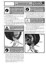
TOOL INTRODUCTION
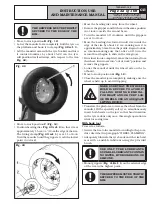
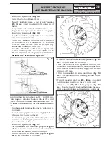
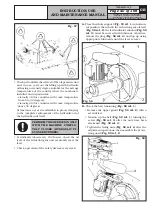
1) Push the lever towards the tool arm (
Fig. 28 ref. 1
)
and place the head (
Fig. 28 ref. 2
) at 90° compared
to the work position.
2) Pulling the check pin outwards (
Fig. 29 ref. 3
) the
head (
Fig. 29 ref. 2
) inserts in its seat.
DURING THIS OPERATION, WITH
THE HAND LEFT FREE, MOVE
THE HEAD (FIG. 29 REF. 2)
DOWNWARDS.
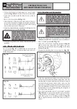
3) At this point, it is possible to rotate the head (
Fig. 29
ref. 2
) as described before.
PAY ATTENTION NOT TO SQUASH
THE HANDS BETWEEN THE TOOL
SUPPORT AND THE ARM!
Fig. 28
Fig. 29
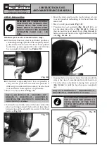
12.6 Tubeless tyres
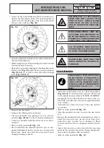
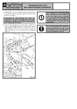
12.6.1 Bead breaking
NEVER PLACE ANY PART OF YOUR
BODY BETWEEN THE TOOL UNIT
AND THE TYRE.
7522-M001-14_P
GG40256.11SL - GG40256.11ST - GG40256.15
GG40256T.15 - GG40256A.15 - GG40256D.15
GG40256TD.15 - GG40256.15SL - GG60360.15
GG60360T.15 - GG60360A.15 - GG60360D.15 - GG60360TD.15

