20
5.
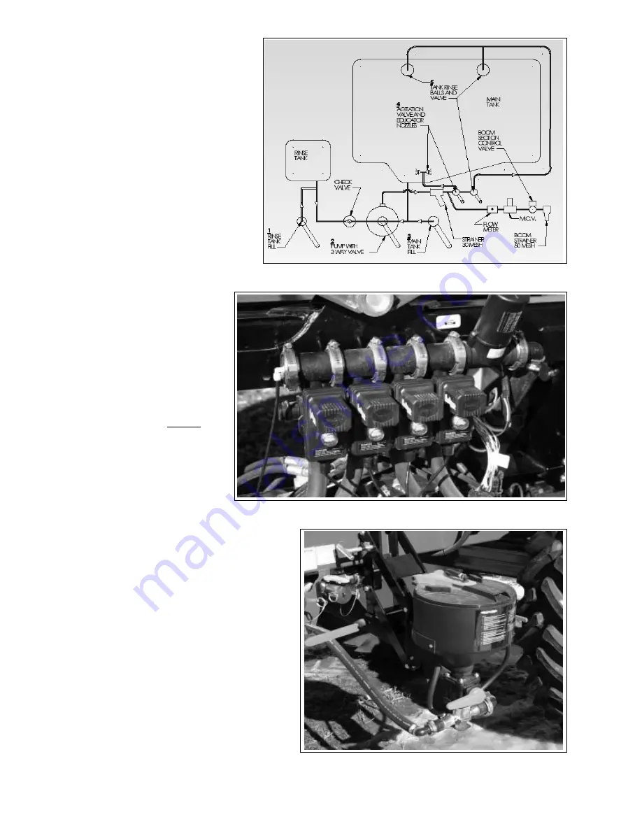
Circuit Diagram:
The valves in the chemical circuit
are used when filling, washing/
rinsing or operating the sprayer.
Refer to Section 4.10 to deter-
mine how the valves should be
set.
1. Main Sump
2. Bottom Fill
3. Pump Intake
4. Wash
5. Agitation
6. Main Tank Rinse Tank
7. Rinse Tank Fill
Fig. 7 CHEMICAL CIRCUIT
6.
Chemical Circuit Valves:
The chemical circuit is
designed with 3 or 4 valves
for controlling and directing
the flow of fluid in the circuit.
Refer to Section 4.10 to
determine how the valves
should be set.
(3 on 60 and 90 )
(4 on 80,88,100
shown
)
(4 on 120)
Fig. 8 CIRCUIT VALVES
Fig. 9 EDUCTOR TANK
(6 on 132)
7.
Eductor Tank (Optional):
The optional eductor tank
system is designed with
drain and rinse valves.
Use as appropriate when
adding chemcial through
this tank.
NOTE
See page 45 Opera-
tional Instructions.
Summary of Contents for Fast Sprayers 9500 Series
Page 68: ...63 Fig 62 BOOM TILT PIVOT 3 Grease boom tilt pivot 1 location each boom Left Right...
Page 78: ...73 This page left blank...
Page 88: ...7 4 CHEMICAL CIRCUIT SCHEMATIC 82...
Page 89: ...7 5 ELECTRICAL SCHEMATIC CABLE 10 CONSOLE 3 OR 6 BOOM SCS 440 450 CONSOLES...
Page 90: ...CABLE 33 FLOW CONTROLLER 3 OR 6 BOOM VALVES 84...
Page 92: ...86 7 7 9500 SERIES 5 FUNCTION HYDRAULIC CAB BOX 9600 SERIES 60...
Page 93: ...7 8 9500 SERIES 5 FUNCTION CAB BOX WIRING 9600 SERIES 60...
Page 94: ...7 9 9600 SERIES 80 100 6 FUNCTION HYDRAULIC BLOCK 88...
Page 95: ...7 10 9600 SERIES 80 100 6 STATION CAB BOX...
Page 96: ...7 11 9600 SERIES 80 100 6 STATION CAB BOX WIRING 90...
Page 97: ...7 12 PARTS LIST FOR YAW BLOCK 91 7 12 9500 SERIES 120 132 YAW BLOCK...
Page 98: ...7 13 9500 SERIES 120 132 YAW BLOCK HARNESS 92...
Page 99: ...7 14 9500 SERIES 120 132 YAW CAB BOX...
Page 100: ...7 15 9500 SERIES 120 132 YAW CAB BOX WIRING 94...
Page 102: ......
Page 103: ......


