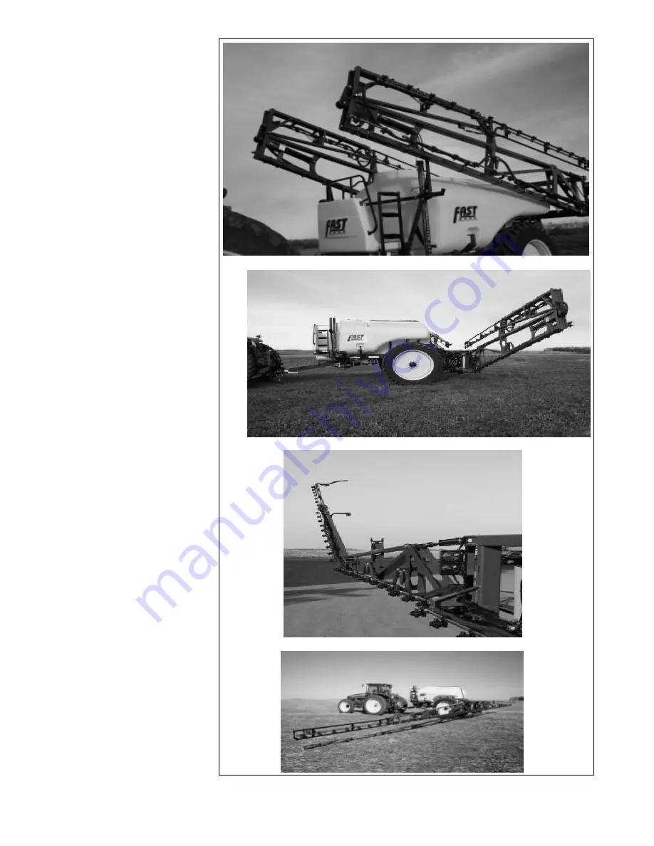
6. Be sure there is
sufficient space to
swing the booms into
their field position.
7. Start the tractor and
run at 1/3 throttle to
provide oil for boom
position cylinders
(Refer to Section 4.6
for Controller Switch
Functions).
8. Raise booms up to lift
them out of their
cradles.
9. Extend inner booms
out until they are 90° to
the frame. Watch for
any interference.
10. Pivot outer booms out
into their fully extended
position.
11. Lower boom to its
lowest position.
12. Be sure foam marker
cup is hanging down.
13. Reverse the above
procedure when
converting from field to
transport configuration.
55
Clearing Cradle
Inner Boom Extending
Outer Boom Extension
Extended
Fig. 56 EXTENDING BOOMS
Summary of Contents for Fast Sprayers 9500 Series
Page 68: ...63 Fig 62 BOOM TILT PIVOT 3 Grease boom tilt pivot 1 location each boom Left Right...
Page 78: ...73 This page left blank...
Page 88: ...7 4 CHEMICAL CIRCUIT SCHEMATIC 82...
Page 89: ...7 5 ELECTRICAL SCHEMATIC CABLE 10 CONSOLE 3 OR 6 BOOM SCS 440 450 CONSOLES...
Page 90: ...CABLE 33 FLOW CONTROLLER 3 OR 6 BOOM VALVES 84...
Page 92: ...86 7 7 9500 SERIES 5 FUNCTION HYDRAULIC CAB BOX 9600 SERIES 60...
Page 93: ...7 8 9500 SERIES 5 FUNCTION CAB BOX WIRING 9600 SERIES 60...
Page 94: ...7 9 9600 SERIES 80 100 6 FUNCTION HYDRAULIC BLOCK 88...
Page 95: ...7 10 9600 SERIES 80 100 6 STATION CAB BOX...
Page 96: ...7 11 9600 SERIES 80 100 6 STATION CAB BOX WIRING 90...
Page 97: ...7 12 PARTS LIST FOR YAW BLOCK 91 7 12 9500 SERIES 120 132 YAW BLOCK...
Page 98: ...7 13 9500 SERIES 120 132 YAW BLOCK HARNESS 92...
Page 99: ...7 14 9500 SERIES 120 132 YAW CAB BOX...
Page 100: ...7 15 9500 SERIES 120 132 YAW CAB BOX WIRING 94...
Page 102: ......
Page 103: ......


