Appendix - Diagrams
ComTec GmbH
Appendix 8-4
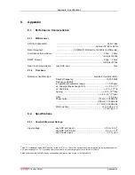
Input HIGH voltage:
........................................................................................... min. 2.0 V
Input LOW voltage:
.......................................................................................... max. 0.8 V
Output LOW voltage:
I
Out LOW
= 8mA .................................................................. max. 0.4 V
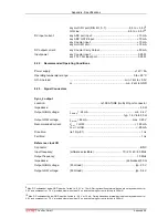
Auxiliary I/O 1..3
Connector: ...................................................................................................
BNC
Pull-up resistor :
(ref. Fig. 3.8) ............................................................................10 k
Ω
Serial termination resistor:
(ref. Fig. 3.8) ..............................................................................33
Ω
Input HIGH voltage:
(at IC pad)
13
..................................................................... min. 2.0 V
Input LOW voltage:
(at IC pad) ....................................................................... max. 0.8 V
Output HIGH voltage:
(at IC pad) I
OutHIGH
= -4.0mA ............................................. min. 2.4 V
Output LOW voltage:
(at IC pad) I
OutLOW
= 8.0mA .............................................. max. 0.4 V
Counters 1…8
Connector:
.....................................................15 pin high-density female D-SUB
Count frequency:
.................................................................................... max. 100 MHz
Location of Carry outputs:
........................................................................ ADC GATE connector
Input Impedance:
..................................................................................... 50
Ω
/ 0.25 W
Input pulse width:
(high or low).........................................................................min. 5 ns
Input HIGH voltage:
........................................................................................... min. 2.0 V
Input LOW voltage:
.......................................................................................... max. 0.8 V
Output impedance:
(series resistor, Carry outputs)...................................... 33
Ω
/ 0.1 W
Output HIGH voltage:
I
OH
= -0.1 mA ..................................................................... min. 3.1 V
Output LOW voltage:
I
OL
= 0.1 mA...................................................................... max. 0.2 V
13 Note: input and output voltages are measured at the internal logic pads not at the external connectors. Thus, the corresponding
pull and series resistors must be considered to get the external voltages

