background image

www.FastListParts.com

10

888-999-7715

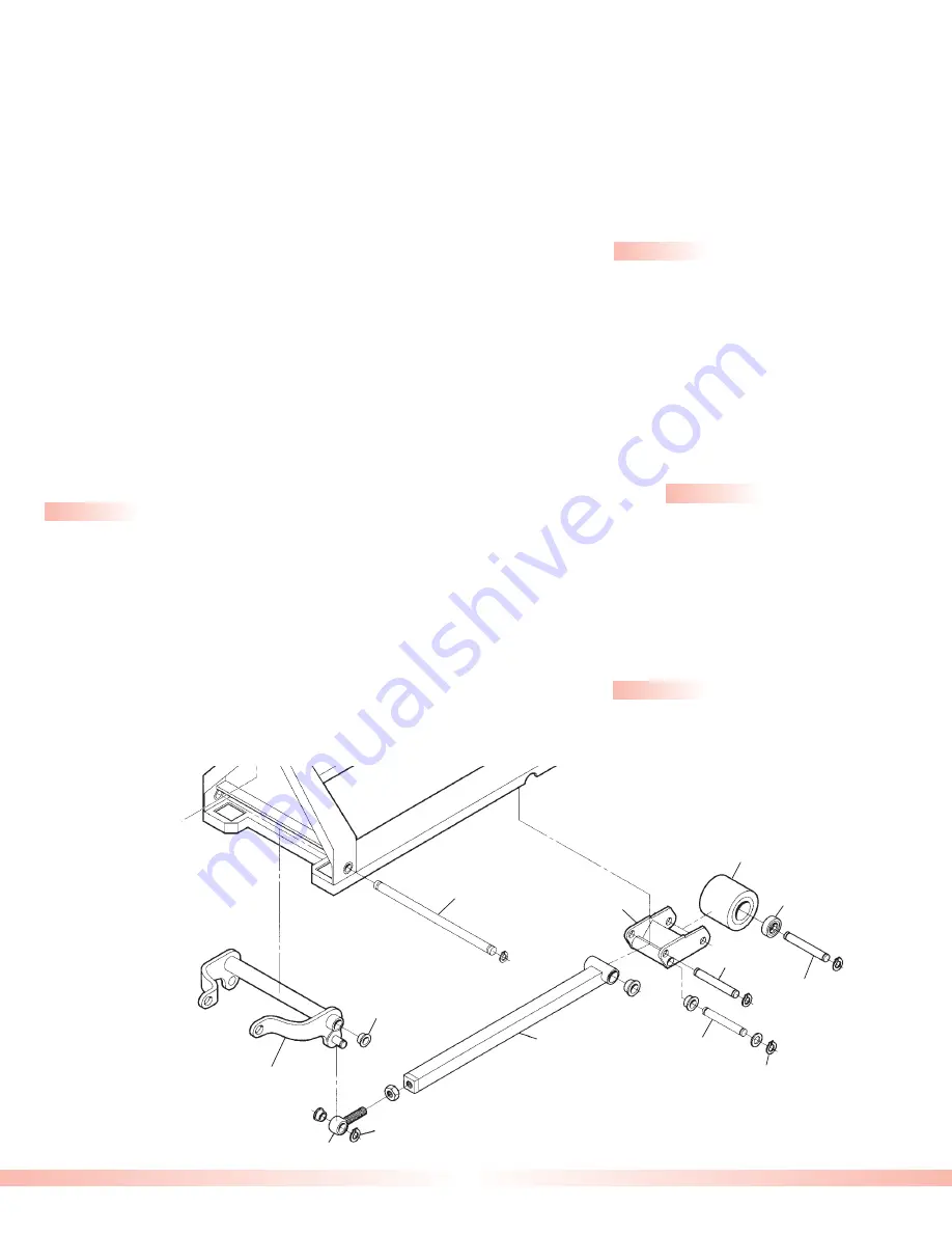
Push Rod 

Axle

Snap Ring

Snap Ring

Eyebolt

Push Rod

Push Rods

Inspection

When inspecting the push rods, look for broken or cracked welds, bends, missing roll pins and worn bushings. It is best to

mark the position of the eyebolt and nut in relation to the push rod to ensure proper adjustment during installation.

Bearing

Bushing

Load Roller

Load Roller 

Axle

Pivot

Axle

Lifting Link Shaft

Lifting Link

Bracket

Removal - T Series

Standard height

- Fully lower the jack and then turn the

jack over so that the undercarriage is facing up. Remove

one of the snap rings on the pivot axle and drive the pivot

axle out of the bracket and frame. Remove one of the snap

rings on the push rod axle and drive the axle out of the

bracket. Loosen the set screw holding the eccentric in the

proper adjustment, remove the snap ring securing the

eccentric to the lifting link and drive the eccentric out of

the lifting link through the access hole in the frame. It is

helpful to mark the adjustment of the eccentric for easier

adjustment of the push rods during assembly. 

(25 minutes)

Lowered height

- Fully lower the jack and then turn the

jack over so that the undercarriage is facing up. Drive out

the roll pin fastening the pivot axle to the load roller

bracket and remove the pivot axle. Drive the roll pin out

that fastens the push rod axle to the load roller bracket

and remove the axle. Unscrew the push rod from the eye

bolt. it is helpful to mark the adjustment of the eye bolt for

proper installation. (20 minutes)

Removal - E Series

Standard height

- Fully lower the jack and then turn the

jack over so that the undercarriage is facing up. Remove

one of the snap rings on the pivot axle and drive the pivot

axle out of the bracket and frame. Remove one of the snap

rings on the push rod axle and drive the axle out of the

bracket. Loosen the nut and unscrew the push rod from

the eye bolt. It is helpful to mark the adjustment of the eye

bolt for proper installation. (20 minutes)

Lowered height

- Fully lower the jack and then turn the

jack over so that the undercarriage is facing up. Drive the

roll pin fastening the pivot axle to the load roller bracket

out and remove the pivot axle. Drive the roll pin that

fastens the push rod axle to the load roller bracket out

and remove the axle. Unscrew the push rod from the eye

bolt. It is helpful to mark the adjustment of the eye bolt for

proper installation. (20 minutes)

E Series - Standard Height

Summary of Contents for Rol-Lift T Series

Page 1: ...ifficult Pallet jack parts are inexpensive and easy to replace To ensure maximum life from the jack always replace the parts that are broken or worn Remember that all parts on a pallet jack depend on...

Page 2: ...www FastListParts com 2 888 999 7715...

Page 3: ...ucts of L L Fabrications Contents 2 2 2 3 3 4 6 7 8 10 12 13 14 15 15 Suggested Assemblies Commonly Used Tools Helpful Reminders Axles Bushings Load Rollers and Load Roller Brackets Steer Wheels and A...

Page 4: ...axle always use a pin punch Always replace old roll pins and snap rings Replace accessible bushings whenever the jack is torn down www FastListParts com 4 888 999 7715 Suggested Assemblies to Save Rep...

Page 5: ...er material and are expendable It is recommended that anytime the jack is torn down to a point where the bushings are accessible they be replaced This will ensure longer life of the jack and will redu...

Page 6: ...eplacement If the wheel has cracks loose tread or does not turn freely replace both wheels Always change the wheels in pairs to reduce uneven wear New load rollers have an outside diameter of 3 or 3 1...

Page 7: ...racket and drive the axle out 15 minutes Installation Load roller brackets Standard height With the jack on its side insert the axle through the bracket and the push rod Secure it in place with the sn...

Page 8: ...ll be free to remove 15 minutes Lowered height Turn the jack onto its side and remove the steer wheels Remove the snap ring on the pin that fastens the axle to the stem of the hydraulic unit Punch the...

Page 9: ...uring the upper thrust bearing assembly in place and lift the frame off of the ram Pull the hydraulic unit out of the traverse with the traverse bearing Punch out the roll pins that fasten the shoulde...

Page 10: ...he jack and then turn the jack over so that the undercarriage is facing up Drive out the roll pin fastening the pivot axle to the load roller bracket and remove the pivot axle Drive the roll pin out t...

Page 11: ...to adjust as needed Assemble the eye bolt and the lifting link with the pin and its snap rings Turn the jack over and test the adjustment Keep adjusting until both forks hit bottom at the same time 25...

Page 12: ...Remove the snap ring on the eccentric and pull the eccentric out through the access hole in the side of the frame Remove the snap ring on the lifting link shaft Use a hammer and punch to drive the sh...

Page 13: ...in the frame Insert the lifting link shaft and secure it with its snap ring Attach the push rod see Push Rods and the load roller bracket see Load Roller Brackets Turn the jack upright and install the...

Page 14: ...ce to secure the handle 5 minutes Hand Control Removal Remove the locking nut and the adjustment screw in the fulcrum bar This will allow the glide pin and the ball to slide out of the way and allow r...

Page 15: ...not to completely remove it Pump the handle slowly to raise the jack then turn the adjusting screw in until the jack stops raising Now turn the adjusting screw an additional 1 4 of a turn and tighten...

Page 16: ...echnical assistance The ram is chromed and the pump piston polished to a fine finish for maximum seal life and minimum oil leakage If you see these surfaces nicked or pitted this will cause the unit t...

Page 17: ...ove the handle if necessary see Handle Removal 45 minutes Installation Slide the stem of the hydraulic unit into the traverse with the lower thrust bearing already in place on the stem Insert the top...

Reviews: