background image

Electric Control System

Page 71

TANK SYSTEMS

to “Rinse Water” or “Rinse Tank” 
(depending on which control switch your 
sprayer has).

4. Slowly open the “Fast Fill” valve marked 
as “Valve F” and let run until rinse tank is 
full. Turn off “Fast Fill” valve. There is a 
breather hose on the rinse tank to allow air 
to escape.

IMPORTANT:

 If you are filling with a high 

volume transfer pump, be careful NOT to 
open the “Fast Fill” valve to full flow.

5. Disconnect the fill hose and replace the 
dust cap. Be careful removing the fill hose 
from the connector - there could be some 
liquid in the line.

Filling With Sprayer Pump

Your sprayer has the ability to fill the clean 
water rinse tank its self by using the 
sprayer product pump. Your sprayer is 
equipped with a 2” male fast fill connector 
and a ON/OFF valve (identified as “Valve 
F”) located on the left side of the sprayer, 
directly behind the step.

Fill as follows:

1. Connect the fill hose to the 2” connec-
tor.

2. Open the water supply valve to fill the 
hose.

IMPORTANT:

 The water source MUST be 

higher than the sprayer pump. NEVER run 
the sprayer pump dry. The sprayer pump 
will not draw water from a source lower 
than the pump, until the pump is primed.

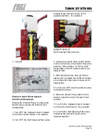
3. Located under the operator platform on 
the left side of the sprayer is an electric 3 

way ball valve. Directly behind this valve is 
a manual ON/OFF valve with a yellow 
handle (1). Turn this valve “OFF” (handle 
pointed toward rear of sprayer).

4. Open the “Fast Fill” valve marked as 
“Valve F.”

5. Start the product pump and run at full 
capacity.

6. Slowly open the “Rinse Tank” valve 
marked as “Valve A” located on the front 
control stand and let run until the rinse 
tank is full. Turn off the “Rinse Tank Fill” 
valve. There is a breather hose on the 
rinse tank to allow air to escape.
7. Stop the product pump.

8. Close the “Fast Fill” valve.

9. Turn the valve under the platform “ON” 
(handle pointed toward right side of 
sprayer).

10. Shut off the external water source.

11. Disconnect the fill hose and replace 
the dust cap. Be careful removing the fill 
hose from the connector - there could be 
some liquid in the line.

Summary of Contents for BW500

Page 1: ...FAST Global Solutions Inc FAST BW500 BW750 Trailer Sprayer Made in U S A BW500 BW750 Trailer Sprayer OPERATION AND MAINTENANCE MANUAL March 2018 Original...

Page 2: ...FAST Global Solutions Inc FAST BW500 BW750 Trailer Sprayer Made in U S A...

Page 3: ...ce Tires Safely 14 Dispose of Waste Properly 15 Handle Agricultural Chemicals Safely 15 Handle Chemical Products Safely 16 Operate Safely 17 Use Safety Lights and Devices 17 Keep Riders Off Machine 17...

Page 4: ...s 44 HC Boom Hydraulic Hose and Electrical Connections 44 HC Boom Electrical Connections 44 Sprayer Accessories 45 Unhitching Sprayer From Tractor 45 Sprayer Accessories 46 Foam Marker Switch Box 46 F...

Page 5: ...inse Tank 67 External Sight Gauge 67 Rinse Tank Flush System Optional 68 Manual Control System 68 Electric Control System 70 Cleaning The Sprayer 72 Long Term Shutdown 73 Electric Control Rinse System...

Page 6: ...Replace Hydraulic Hoses 93 Tightening Hardware 93 Metric Bolt and Screw Torque Values 94 Unified Inch Bolt and Screw Torque Values 95 Face Seal Fittings Assembly and Installation All Pressure Applica...

Page 7: ...ddressed as follows FAST AG Solutions 4130 Commerce Boulevard Windom MN 56101 This warranty shall expire one 1 year after the date of delivery of the new machinery If these conditions are fulfilled FA...

Page 8: ...ctions ____Check Tire Pressure ____Frame and Wings Level ____Monitors and Controllers Function ____Wiring Harness Connected I have thoroughly instructed the buyer on the above described equipment whic...

Page 9: ...0 TRAILER SPRAYER SPRAYER APPLICATOR SERIAL NUMBER __________________________________ DATE PURCHASED ______________ _____ __________ TANK SIZE _____________________ BOOM LENGTH________________________...

Page 10: ...Warranty Registration Page 4 WARRANTY REGISTRATION FORM...

Page 11: ...n in both metric and customary U S unit equivalents Use only correct replacement parts and fasteners Metric and inch fasteners may require a specific metric or inch wrench RIGHT HAND AND LEFT HAND sid...

Page 12: ...t on this SPRAYER will relieve the manufacturer of all liability for any resulting damage or injury WARRANTY is provided as part of FAST s support program for customers who operate and maintain their...

Page 13: ...MAINTENANCE section in this manual Inspect to be sure all nuts have been tightened to proper torque and all cotter pins spread Tires are properly inflated Tighten wheel bolts to specified torque Adjus...

Page 14: ...r s manual to customer and explain all operating adjustments Make customer aware of all safety precautions that must be followed while using this machine When machine is transported on a road or highw...

Page 15: ...tood If possible operate machine to see that it is functioning properly Acquaint customer with any special attachment which will help do a better job Go over entire machine for loose or missing hardwa...

Page 16: ...Owner Register Page 10 FOREWARD Owner Register Name Model Number Post Office P I N Number County State Date Purchased...

Page 17: ...tructions Carefully read all safety messages in this manual and on your machine safety signs Keep safety signs in good condition Replace missing or damaged safety signs Be sure new equipment component...

Page 18: ...tention of the operator Do not wear radio or music headphones while operat ing machine Protect Against Noise Prolonged exposure to loud noise can cause impairment or loss of hearing Wear a suitable he...

Page 19: ...efore use If there is a failure in hydraulic system unsupported raised equipment could suddenly lower causing serious per sonal injury or death If support is not available completely lower wings and f...

Page 20: ...t cylinders and hydraulic lock up valves should be inspected frequently for leakage kinking cuts cracks abrasion blisters corrosion exposed wire braid or any other signs of wear or damage Worn or dama...

Page 21: ...r waste onto the ground down a drain or into any water source Air conditioning refrigerants escaping into the air can damage the Earth s atmo sphere Government regulations may require a certified air...

Page 22: ...marked con tainers or to containers used for food or drink Store chemicals in a secure locked area away from human or livestock food Keep children away Always dispose of containers properly Tri ple ri...

Page 23: ...or seat only If chemicals are used follow manufac turer s recommendations for handling and storage Tow machine behind a properly equipped tractor only Use Safety Lights and Devices Prevent collisions...

Page 24: ...in Loss of control of the tractor implement combination Reduced or no ability to stop during brak ing Implement tire failure Damage to the implement structure or its components Use additional caution...

Page 25: ...in to the tractor drawbar support or other specified anchor location Provide only enough slack in the chain to permit turning Tow Loads Safely Stopping distance increases with speed and weight of towe...

Page 26: ...height and width restrictions to avoid collision with overpasses or other road users Always fold wings fully If wing fold cylin ders are removed chain wings together to prevent accidental lowering Fu...

Page 27: ...s section Shift tractor into a lower gear when trans porting down steep slopes or hills never coast Stop slowly Wide turns may be required with machine in tow Use caution in traffic and in con gested...

Page 28: ...gns Replace missing or damaged safety signs Use this operator s manual for correct safety sign placement There can be additional safety information contained on parts and components sourced from suppl...

Page 29: ...ations Safety signs and locations on machine are shown in the following illustrations Famil iarize yourself with safety signs type of warning and area or particular function related to that area that...

Page 30: ...Safety Sign Locations Page 24 SAFETY K L K L...

Page 31: ...Safety Sign Locations Page 25 SAFETY Decal A Decal B Decal C Decal D...

Page 32: ...Safety Sign Locations Page 26 SAFETY Decal E Decal F Decal G Decal H Decal I Decal J...

Page 33: ...Safety Sign Locations Page 27 SAFETY Decal K Decal L...

Page 34: ...ns 1 Yellow Reflector Qty 2 Part No 907220 Not Shown One On Each Side Of Hitch 2 Yellow Reflector Qty 2 Left Side Shown Part No 907220 3 SMV Emblem Part No 907224 4 Red Reflector Qty 2 Left Side Shown...

Page 35: ...a public roadway In regions or countries that have national certification requirements for roadway transport it may be impossible for this implement to be approved for such roadway transport The cust...

Page 36: ...endations 3 Be sure that machine is properly attached to tractor Be sure that a mechanical retainer is installed through drawbar pin and safety chain is installed 4 Inspect all hydraulic lines hoses f...

Page 37: ...one side than other Increased penetration on one side will result in side draft of machine Inflate tires to shown specification Checking Wheel Nuts Check tightness of all wheel nuts during first week...

Page 38: ...eel and hub assembly to the sprayer frame 6 Slide the wheel and hub assembly in or out to the desired distance Measure from the centerline of the sprayer to the center line of the tire DO NOT exceed t...

Page 39: ...anges on the sprayer tongue b Raise or lower the hitch or rotate the hitch 180 to a position that will ensure that the sprayer is as level as possible c Insert all four bolts through the flanges on th...

Page 40: ...the storage mount on the sprayer frame d Secure in place with the pin and clip 1 Pin and Clip 2 Jack In Stored Position Important Always secure the jack in the storage position before beginning any op...

Page 41: ...s If an accident occurs see a doctor imme diately Any fluid injected in skin must be surgically removed within a few hours or gangrene may result Doctors unfamiliar with this type of injury should ref...

Page 42: ...red up gravity down BW750 60 double acting controls all folding functions B I Return Orange BW500EF EFT Main Lift single acting powered up gravity down BW750 60 double acting controls all folding func...

Page 43: ...When storing machine keep safety chain up off ground and hook to machine sup port assembly on hitch Always replace a safety chain if one or more links or end fittings are broken stretched or otherwis...

Page 44: ...by turning crank handle to lower jack Wiring Harness and Hose Storage Position 2 Disconnect wiring harness and place in storage position CAUTION Prevent serious injury or death Relieve hydraulic syst...

Page 45: ...narrow gates KNOW transport and width of your machine See SPECIFICATIONS sec tion Travel at a reasonable and safe speed REDUCE speed over rough or uneven ter rain slopes and when turning BE SURE SMV...

Page 46: ...intensity Keep Riders Off Machine CAUTION Keep riders off Riders are subject to injury such as being struck by foreign objects and being thrown off machine Riders obstruct operator s view resulting i...

Page 47: ...M tractor PTO output shafts Connect Optional 1000 RPM sprayer pumps ONLY to 1000 RPM tractor PTO output shafts 5 Pull the collar on the tractor end of the driveline to the rear toward the sprayer and...

Page 48: ...aulic hoses should ONLY be used when sprayer is disconnected from the tractor and being stored Hydraulic hoses MUST always be connected to tractor during transport of sprayer Control Box Installation...

Page 49: ...procedure Verify the values and note them in the controller book for reference 6 Complete the final assembly and make the final connections Test system to make sure it is working properly Hydraulic Ho...

Page 50: ...e if your tractor has this type of hydrau lics Connect sprayer hydraulic hoses to the tractor hydraulic system When the HC boom is in use the hydraulic valve on the tractor MUST be locked open to assu...

Page 51: ...s STOPPED and parking brake is applied WARNING Before disconnecting the PTO shaft make sure that the tractor motor has stopped turning before getting off the tractor 1 Park sprayer on a firm level sur...

Page 52: ...ied with the unit for installation instructions Connect the foam marker kit as follows Connect the WHITE wire to the Positive 12 volt power source on your tractor Connect the BLACK wire to the Negativ...

Page 53: ...s away Clean reflectors SMV and lights before transporting Attach securely to towing unit using a hardened pin with a retainer and a safety chain Do not exceed a safe travel speed Use hazard flasher o...

Page 54: ...t of torque 2 Then follow normal servicing and main tenance schedule as defined in Mainte nance Section Pre Operation Checklist Efficient and safe operation of the Fast sprayer requires that each oper...

Page 55: ...ing Repeat the above process and average the times that were measured Use the following equation or the table to determine ground speed Useful Formulas and Conversions GPA Application rate in gallon p...

Page 56: ...28 N Determine the correct nozzle size as follows GPA solution x Conversion factor GPA from table 20 GPA 28 x 1 13 22 6 GPA water The sprayer operator should choose a nozzle size that will supply 22...

Page 57: ...m maximum NOTE Contact factory for an optional flow control for use with high flow open center system Two or three remote outlets are required to operate the sprayer 1 BW500 EF EFT main lift single ac...

Page 58: ...F a boom section the pressure of liquid supplied to the other two boom sections will increase because the same volume of liquid is being pumped through fewer nozzles The operator must use the pressure...

Page 59: ...not have a self cleaning filter the agitation throttling valve will be located near the front left corner of the sprayer platform 1 Agitation Throttling Valve If the sprayer has a self cleaning filte...

Page 60: ...e boom and are attached to the ON OFF valves There will be one filter per ON OFF valve and are equipped with 50 mesh screens Optional size screens are available through your FAST dealer WARNING Wear p...

Page 61: ...Cleaning Filter Optional Refer to the Maintenance section of this manual for filter maintenance interval and procedures A self cleaning filter is an optional accessory This filter has a throttling val...

Page 62: ...nfiguration 2 Fast Fill via transfer pump Optional Group A 2 Fast Fill via transfer pump or sprayer pump Optional Group C NOTE If Group C is ordered you have the option of manual or Electric controls...

Page 63: ...sprayer product pump Your sprayer is equipped with a 2 male fast fill connector and a ON OFF valve identified as Valve F located on the left side of the sprayer directly behind the step Fill as follo...

Page 64: ...ard rear of sprayer With Electric Control Rinse System Located under the operator platform on the left side of the sprayer is an electric three way ball valve Directly behind this valve is a manual ON...

Page 65: ...nk If the pressure drops adjust the pressure setting at the sprayer control box 9 Check for uniform flow at all the spray nozzles The sprayer is now ready for calibration Priming The Sprayer Equipped...

Page 66: ...red RPMs and pressure 9 While parked collect the liquid from the nozzle Hold a container graduated in ounces below a nozzle Record the output for the same time period as the average driving time deter...

Page 67: ...rst time each year Check all the tie down straps for proper tightness 1 Fill all tanks completely 2 Check the straps for proper tightness Straps should be snug around the tank 3 If straps require tigh...

Page 68: ...Tank Tie Down Straps Page 62 VALVE SETTING INSTRUCTIONS VALVE SETTING INSTRUCTIONS Valve Settings For Accessory Kits Refer To The Operator s Manual For Detailed Instructions...

Page 69: ...d run at rated speed 4 OPEN the Chemical Fill Control valve 5 If you are going to use the measuring marks on the chemical inductor tank to measure the amount of chemical being added make sure the valv...

Page 70: ...or Tank Cover 2 Chemical Inductor Tank 3 Chemical Inductor Venturi 4 Valve At Bottom Of Inductor Tank 5 Agitation Control Valve 6 Chemical Fill Control Valve 7 Hand Rinse Gun NOTE Some chemicals tend...

Page 71: ...hand gun can be supplied with water Standard system via the product pump Optional electric system via a 12 volt electric pump Standard System The standard system supplies water from the sprayer tank...

Page 72: ...he control center 3 Remove the hand gun from the storage bracket and rinse the chemical inductor tank 4 When finished turn OFF the electric switch point the hand gun into the chemical inductor tank an...

Page 73: ...cals or other contaminates 1 Fresh Water Tank 2 Fresh Water Tank Fill 3 Fresh Water Tank Petcock External Sight Gauge An external sight gauge is available for the product tank of your sprayer This sig...

Page 74: ...m lines and leave the product tank undisturbed Rinse the product pump product tank controls and boom lines There are two types of control systems available for the rinse system Manual controls located...

Page 75: ...rayer Pump Your sprayer has the ability to fill the clean water rinse tank its self by using the sprayer product pump Your sprayer is equipped with a 2 male fast fill connector and a ON OFF valve iden...

Page 76: ...Tank The 50 gallon rinse tank can be filled 3 dif ferent ways Fill Through Top Lid 1 Remove the lid from the top of the rinse tank Fill the tank using a garden hose or similar means 2 Replace the lid...

Page 77: ...tor 2 Open the water supply valve to fill the hose IMPORTANT The water source MUST be higher than the sprayer pump NEVER run the sprayer pump dry The sprayer pump will not draw water from a source lo...

Page 78: ...Rinse System Short Term Shutdown Rinsing the Product Pump Controls and Boom Lines Leaving the Product Tank Undisturbed 1 Turn OFF the Agitation Valve located on the front control stand If so desired...

Page 79: ...aning when changing chemicals Products are available from your FAST dealer 1 Add the recommended amount of Neutralizer to the clean water rinse tank 2 Turn the manual 3 way ball valve identified as Va...

Page 80: ...2 3 Locate the electric rinse control switch on the control box on the tractor Move the switch to Rinse Water or Rinse Tank depending on which control switch your sprayer has 4 Start product pump driv...

Page 81: ...and or Product Tank Rinse switch to the OFF position and the Product Tank Rinse Tank switch to the Product Tank position Standard electric control 6 Drive at normal speed turn complete boom on and sp...

Page 82: ...complete boom until the boom wings clear the transport rest 2 Place the tractor in park and or set the brakes and stop the engine 3 Remove the transport lock from the lift cylinder at the rear of the...

Page 83: ...position on the boom stabilizer arm and put in place on the hydraulic lift cylinder 5 Restart the tractor and lower the boom on to the boom transport rest Transport Lock In Storage Position On Boom S...

Page 84: ...e ignition key and wait for all moving parts to stop before servicing adjusting repairing or unplugging Follow good shop practices Keep service area clean and dry Be sure electrical outlets and tools...

Page 85: ...EP performance Also acceptable is an SAE multi purpose lithium base grease Use grease based on NLGI consistency numbers and the expected air temperature range during the service interval IMPORTANT So...

Page 86: ...d from dust moisture and other contamination Store containers on their side to avoid water and dirt accumulation Make certain all containers are properly marked to identify their contents Properly dis...

Page 87: ...r lubrication of the pump NEVER operate the sprayer unless ALL shielding is in place and secure Contact with rotating parts can cause death or personal injury Your sprayer may be equipped with one of...

Page 88: ...oom Mounting Arm Pivot Points Lubricate ALL the pivot points on each mounting arm and the center pivot using a good quality grease The center pivot is located directly behind the slow moving vehicle S...

Page 89: ...y grease Clean off grease fittings before attaching grease gun Wipe up any excess grease when finished Secondary Boom Wing Pivot Point Three at Top 1 Grease Fittings Secondary Boom Wing Pivot Point On...

Page 90: ...bricate the boom tower slides with liquid graphite If operating in extremely dusty conditions shorten the lubrication interval as required 1 Boom Tower Slides 200 Hour Lubrication Interval Wheel Beari...

Page 91: ...Always wear gloves and eye protection while servicing the sprayer To manually clean the self cleaning filter 1 Make sure the product pump is turned OFF 2 Close the emergency shut off valve under the...

Page 92: ...es on the sprayer to ensure you have clean water through the entire system NOTE The pressure gauge hose is supplied from the rear of the sprayer and is a dead end circuit The following procedure is re...

Page 93: ...r bowl at the bottom of the tank and flush tank with warm water 2 Replace the filter bowl Fill the tank with at least 2 gallons of hot water Turn on the machine and allow to run out each side until no...

Page 94: ...ts out decreases the tension The springs are located between the primary and secondary boom wings Boom Level If the boom does not hang level secure the boom with an overhead hoist or other suitable me...

Page 95: ...ed or lowered Secure the boom wing assembly with an overhead hoist or other suitable means Loosen the four nuts at the pivot between the center boom and the primary boom wing Use the overhead hoist to...

Page 96: ...the tension on the breakaways is too great the boom may be damaged if it strikes a stationary object Adjust the tension as needed by turning the turnbuckles located on the front side of the boom wings...

Page 97: ...of grease oil or debris On self propelled equipment disconnect battery ground cable before making adjustments on electrical systems or weld ing on machine On towed implements disconnect wiring harnes...

Page 98: ...chment operator s manual Avoid High Pressure Fluids Inspect hydraulic hoses periodically at least once per year for leakage kinking cuts cracks abrasion blisters corrosion exposed wire braid or any ot...

Page 99: ...r death could occur If hoses are to be fabricated ensure hoses are rated at no less than 82 737 kPa 827 bar 12 000 psi burst pressure according to SAE standard J517 100R17 hose specification Incorrect...

Page 100: ...250 1650 2850 2100 3200 2350 4050 3000 3750 2770 4750 350 0 Torque values listed are for general use only based on the strength of the bolt or screw DO NOT use these values if a different torque value...

Page 101: ...550 3350 Torque values listed are for general use only based on the strength of the bolt or screw DO NOT use these values if a different torque value or tightening procedure is given for a specific ap...

Page 102: ...fit ting 2 Install a thimble over the fitting threads to protect the O ring from nicks 3 Slide the O ring over the thimble into the turned down section of the fitting 4 Remove thimble Face Seal Strai...

Page 103: ...g 8 Inspect all hydraulic hoses couplers and fittings Tighten any loose fittings Replace any hose that is damaged or separating from crimped end of a fit ting 9 Inspect all liquid lines and connection...

Page 104: ...ation and Maintenance for details of service Copy this page to continue record Action Code CL Clean L Lubricate Item Hours Service d By 8 hours Or Daily L Flip WingHinges L Inner WingHinges CL Straine...

Page 105: ...Spray system pressure low Primary filter beginning to plug Clean filter Pressure regulating or throttling valve out of Adjust valve Spray tips to large Verify spray tip size Speed to slow Increase tr...

Page 106: ...ratic spray system pressure Air leaks in suction line Tighten clamp check hoses for cracks or breaks Tank getting empty Refill tank Vacuum developing in tank Remove tank cover clean tank vent Spray sy...

Page 107: ...gitation Agitation valve closed Open valve Agitation valve not completely open Open valve Poor tank agitation cont Self cleaning filter ON OFF valve not open Open valve Plugged agitation nozzle s Clea...

Page 108: ...ighten swivel nut until snug 4 To prevent twisting tubes or hoses use two wrenches Place one wrench on connector body and with second wrench tighten swivel nut to torque shown Torque values shown are...

Page 109: ...Hydraulic Fitting Torque Page 103 RAVEN CONSOLE CALIBRATION RAVEN CONSOLE CALIBRATION...

Page 110: ...boom and turn ON the fence row nozzle valve When handle is at a right angle from the valve it is in the OFF position 3 Start the sprayer and spray as normal 4 When finished turn OFF the boom stop the...

Page 111: ...Part 963 March 22 2018 NOTES...

Page 112: ...Part 820041 March 22 2018 FAST GLOBAL SOLUTIONS 4130 Commerce Boulevard Windom MN 56101 1 800 772 9279 Toll Free 1 507 427 3861 Voice 1 507 427 3030 Fax...

Reviews: