background image


11

2.  Safety


^

YOU

 are responsible for the 

SAFE

 operation and 

maintenance  of  your  Fast  Manufacturing,  Inc.  Sprayer. 

YOU must ensure that you and anyone else who is going 

to operate, maintain or work around the Sprayer be familiar 

with the operating and maintenance procedures and related 

SAFETY

 information contained in this manual. This manual 

will  take  you  step-by-step  through  your  working  day  and 

alerts you to good safety practices that should be adhered 

to while operating the sprayer.

Remember, 

YOU

 are the key to safety. Good safety practices 

not only protect you but also the people around you. Make 

these practices a working part of your safety program. 

Be certain that 

EVERYONE

  operating  this  equipment  is 

familiar with the recommended operating and maintenance 

procedures and follows all the safety precautions. Most 

accidents can be prevented. Do not risk injury or death by 

ignoring good safety practices.

•  Sprayer  owners  must  give  operating  instructions 

to operators or employees before allowing them to 

operate the unit, and at least annually thereafter per 

OSHA regulation 1928.57.

•  The most important safety device on this equipment is a 

SAFE

 operator. It is the operator’s responsibility to read 

and understand 

ALL

 Safety and Operating instructions 

in the manual and to follow these. All accidents can be 

avoided.

• 

A person who has not read and understood all operating 

and  safety  instructions  is  not  qualified  to  operate  the 

machine. An untrained operator exposes himself and 

bystanders to possible serious injury or death.

•  Do not modify the equipment in any way. Unauthorized 

modification may impair the function and/or safety and 

could affect the life of the equipment.

•  Think SAFETY! Work SAFELY!

2.1  Safety Alert Symbol And Signal 

Words

This symbol means ATTENTION! BECOME ALERT! YOUR 

SAFETY IS INVOLVED! 


^

The level of risk is indicated by the following signal words: 

^


DANGER


DANGER - Indicates a hazardous situation, 

which, if not avoided, WILL result in death or 

serious injury.

^


WARNING


WARNING - Indicates a hazardous situation, 

which, if not avoided, could result in death or 

serious injury.

^


CAUTION


CAUTION - Indicates a hazardous situation, 

which, if not avoided, could result in minor or 

moderate injury.

NOTICE


NOTICE 

- Indicates a situation that could 

result in damage to the equipment or other 

property.

Summary of Contents for BW750

Page 1: ...BW500 and BW750 Trailer Sprayer OPERATION MANUAL Fast Manufacturing Inc 54859 County Road 44 Mountain Lake MN 56159...

Page 2: ...ritten permission from Fast Manufacturing Inc Parts information in this manual represents components installed when product was manufactured based upon the best available information Modifications mad...

Page 3: ...ecessary addressed as follows FAST MANUFACTURING INC 54859 County Road 44 Mountain Lake MN 56159 This warranty shall expire one 1 year after the date of delivery of the new machinery If these conditio...

Page 4: ..._______________________________ Delivery Date_____________________________________________________________________________________ DEALER INSPECTION REPORT SAFETY ____All Fasteners Tight ____ Safety C...

Page 5: ...draulic Safety 14 2 8 Transport Safety 14 2 9 Storage Safety 15 2 10 Tire Safety 15 2 11 Safety Signs 15 2 12 Sign Off Form 16 2 13 Safety Sign Locations 17 2 14 Reflective Decal Locations 22 3 Delive...

Page 6: ...Sprayer Accessories 32 8 1 Foam Marker Switch Box 32 8 2 Fence Line Kit Right Side Left Side Or Both 32 8 3 In Cab Electric 50 Gallon Rinse System 32 9 Operation 33 9 1 New Operator Or Owner 33 9 2 B...

Page 7: ...roller 55 9 18 Calibrating The Sprayer 55 9 18 1 Teejet Electric Control System 55 9 18 2 Raven Rate Control System Optional 55 9 19 Tank Tie Down Straps 56 9 20 Chemical Inductor Optional 58 9 21 Han...

Page 8: ...1 EF EFT Boom 66 9 30 2 EFT Boom 67 9 30 3 HC Boom 67 10 Service And Maintenance 68 10 1 Service 68 10 1 1 Fluids And Lubricants 68 10 1 2 Daily Lubrication Interval 68 10 1 3 Weekly Lubrication Inte...

Page 9: ...vice Record 75 11 Troubleshooting 76 12 Specifications 79 12 1 Mechanical 79 12 2 Hydraulic Fitting Torque 79 12 3 Raven Console Calibration Information 81 13 Optional Accessories 82 13 1 In Line Filt...

Page 10: ...uires that you and anyone else who will be operating or maintaining the sprayer read and understand the Safety Operation Maintenance and Trouble Shooting information contained in the Operator s Manual...

Page 11: ...thereafter per OSHA regulation 1928 57 The most important safety device on this equipment is a SAFE operator It is the operator s responsibility to read and understand ALL Safety and Operating instru...

Page 12: ...afety signs before using 2 Lower machine to ground place all controls in neutral stop engine set park brake remove ignition key and wait for all moving parts to stop before servicing adjusting repairi...

Page 13: ...serious injury 2 5 Implement Safety Some photographs used herein may show doors guards and shields opened or removed BE SURE that all doors guards and shields are fastened in their proper position bef...

Page 14: ...y worn cut abraded flattened or crimped hoses 4 Do not attempt any makeshift repairs to hydraulic lines fittings or hoses by using tape clamps or cements 5 The hydraulic system operates under extremel...

Page 15: ...ury or death 2 Do not attempt to mount a tire unless you have the proper equipment and experience to do the job 3 Have a qualified tire dealer or repair service perform required tire maintenance 2 11...

Page 16: ...ety Operating and Maintenance information presented in this manual Do not operate or allow anyone else to operate this equipment until such information has been reviewed Annually review this informati...

Page 17: ...ons Safety signs and locations on machine are shown in the following illustrations Familiarize yourself with safety signs type of warning and area or particular function related to that area that requ...

Page 18: ...18...

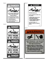
Page 19: ...19 Decal A Decal B Decal C Decal D...

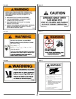
Page 20: ...20 Decal E Decal F Decal G Decal H Decal I Decal J...

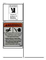
Page 21: ...21 Decal K Decal L...

Page 22: ...Reflector Qty 2 Part No 907220 Not Shown One On Each Side Of Hitch 2 Yellow Reflector Qty 2 Left Side Shown Part No 907220 3 SMV Emblem Part No 907224 4 Red Reflector Qty 2 Left Side Shown Part No 907...

Page 23: ...r Representative s Name _____________________________________________ Date Checklist Filled Out _____________________________________________ Model Number Serial Number 3 2 Delivery Check List The fol...

Page 24: ...e 5 Loosen the nuts on the U bolts securing the wheel and hub assembly to the sprayer frame 6 Slide the wheel and hub assembly in or out to the desired distance Measure from the centerline of the spra...

Page 25: ...or lower the hitch or rotate the hitch 180 to a position that will ensure that the sprayer is as level as possible c Insert all four bolts through the flanges on the sprayer tongue and the hitch Tigh...

Page 26: ...ayer pumps ONLY to 1000 RPM tractor PTO output shafts 5 Pull the collar on the tractor end of the driveline to the rear toward the sprayer and slide the driveline onto the tractor s PTO output shaft a...

Page 27: ...purchase a wiring harness pigtail adaptor from your tractor dealer or Fast Manufacturing Inc Be sure to ONLY connect to tractors with a 12 Volt Positive electrical system 5 4 Electric Sprayer Controls...

Page 28: ...er are marked with colored tie wraps to identify the hoses for proper connection to the tractor The pair of hoses for the fold IN or OUT will have one color and the boom UP or DOWN will be another col...

Page 29: ...m Closed Center Hydraulic system set up to Open Center Hydraulics 1 Locate the valve block at the rear of your sprayer on the rear tower 2 Locate the plug on the left hand end of block remove and inse...

Page 30: ...is unhitched from the tractor 2 Shut down and lockout the power source Refer to Power Source Shutdown Procedure on Page 3 of this manual Follow these procedures to correctly lockout the power source...

Page 31: ...moving objects IMPORTANT NEVER exceed the maximum towing speed of 20 MPH 32 Kmh Reduce speed when turning or traveling on rough or hilly terrain 7 1 Transport Lighting The sprayer is equipped with tra...

Page 32: ...our tractor Connect the BLACK wire to the Negative ground source on your tractor or a good ground 8 2 Fence Line Kit Right Side Left Side or Both Afence line kit is an optional accessory Refer to the...

Page 33: ...ing Inc Sprayer is designed to meter out and distribute liquid chemical or fertilizer and place it where required It is the responsibility of the owner or operator to read this manual and to train all...

Page 34: ...d or in an area with similar surface conditions Minimum lengths of 100 and 200 feet are recommended for measuring speeds up to 5 and 10 miles per hour respectively Determine the time required to trave...

Page 35: ...en selecting nozzles to be used on a boom for broadcast application finding the correct combination of these factors is important The nozzle spray angle and the height of the boom will determine the o...

Page 36: ...36 9 6 Spray Tip Wear...

Page 37: ...2 9 3 1 3 3 3 5 3 6 3 8 4 0 4 1 4 3 AM110015 TDXL 110015 TDCXL 110015 50 mesh screen 20 30 40 50 60 70 80 90 100 110 120 120 130 140 150 0 11 0 13 0 15 0 17 0 18 0 20 0 21 0 22 0 24 0 25 0 26 0 26 0 2...

Page 38: ...0 12 7 13 4 14 1 14 7 15 3 15 9 16 4 5 2 6 4 7 4 8 3 9 1 9 8 10 5 11 1 11 7 12 3 12 9 13 4 13 9 14 4 4 7 5 7 6 6 7 4 8 1 8 7 9 3 9 9 10 4 10 9 11 4 11 9 12 3 12 8 AM11004 TDXL 11004 TDCXL 11004 24 me...

Page 39: ...4 78 9 83 2 87 2 91 1 94 8 98 4 101 8 31 9 39 0 45 1 50 4 55 2 59 6 63 8 67 6 71 3 74 8 78 1 81 3 84 3 87 3 27 9 34 2 39 4 44 1 48 3 52 2 55 8 59 2 62 4 65 4 68 3 71 1 73 8 76 4 22 3 27 3 31 6 35 3 38...

Page 40: ...2 7 2 9 3 0 3 1 3 2 AM110015 TDXL 110015 TDCXL 110015 50 mesh screen 20 30 40 50 60 70 80 90 100 110 120 120 130 140 150 0 11 0 13 0 15 0 17 0 18 0 20 0 21 0 22 0 24 0 25 0 26 0 26 0 27 0 28 0 29 7 9...

Page 41: ...5 10 1 10 5 11 0 11 5 11 9 12 3 3 9 4 8 5 6 6 2 6 8 7 4 7 9 8 3 8 8 9 2 9 6 10 0 10 4 10 8 3 5 4 3 4 9 5 5 6 1 6 5 7 0 7 4 7 8 8 2 8 6 8 9 9 3 9 6 AM11004 TDXL 11004 TDCXL 11004 24 mesh screen 20 30...

Page 42: ...55 8 59 2 62 4 65 4 68 3 71 1 73 8 76 4 23 9 29 3 33 8 37 8 41 4 44 7 47 8 50 7 53 5 56 1 58 6 61 0 63 3 65 5 20 9 25 6 29 6 33 1 36 2 39 1 41 8 44 4 46 8 49 1 51 2 53 3 55 3 57 3 16 7 20 5 23 7 26 5...

Page 43: ...43 9 8 TeeJet Air Induction Spray Tips 9 8 1 20 Inch Spacing At Various Speeds And Pressures...

Page 44: ...0 5 6 5 9 6 6 6 9 7 6 7 9 1 7 3 4 3 7 4 0 4 3 4 6 5 2 5 5 6 1 6 4 7 0 7 3 2 5 3 1 3 4 3 7 4 0 4 2 4 8 5 1 5 7 5 9 6 5 6 8 2 2 2 7 3 0 3 2 3 5 3 7 4 2 4 5 5 0 5 2 5 7 5 9 2 0 2 4 2 6 2 9 3 1 3 3 3 7 4...

Page 45: ...0 52 0 56 0 60 0 67 0 73 0 79 0 85 0 90 0 95 47 54 60 67 72 77 86 93 101 109 115 122 29 33 37 41 44 48 53 58 63 67 71 75 24 28 31 34 37 40 44 48 52 56 59 63 21 24 27 29 32 34 38 41 45 48 51 54 18 3 2...

Page 46: ...1 5 1 7 2 0 2 2 2 2 2 5 2 7 3 0 3 2 3 5 3 7 4 0 1 4 1 6 1 8 2 1 2 1 2 3 2 5 2 7 3 0 3 2 3 4 3 7 1 3 4 5 1 7 1 9 1 9 2 1 2 3 2 5 2 8 3 0 3 2 3 4 1 1 1 3 1 5 1 7 1 7 1 9 2 0 2 2 2 4 2 6 2 8 3 0 1 0 1 2...

Page 47: ...5 0 79 40 45 51 55 60 64 72 78 84 91 96 101 18 21 24 26 28 30 33 36 39 42 45 47 15 17 20 21 23 25 28 30 33 35 37 39 13 2 15 17 18 20 21 24 26 28 30 32 34 11 5 13 0 14 9 16 17 19 21 23 25 26 28 29 9 2...

Page 48: ...3 35 37 39 13 9 16 18 20 21 23 26 28 30 32 34 36 12 9 15 1 17 18 20 21 24 26 28 30 32 34 11 3 13 2 14 7 16 17 19 21 23 25 26 28 29 10 1 11 7 13 0 14 4 16 17 18 20 22 23 25 26 XR11015 SS 15 20 25 30 35...

Page 49: ...49 9 10 TeeJet FloodJet Wide Angle Flat Spray Tips 9 10 1 40 Inch Spacing At Various Speeds And Pressures...

Page 50: ...EFT folds wings in or out 3 For optional hydraulic drive centrifugal pump Note Always place hydraulic control lever in detent to provide a constant flow of oil to pump drive motor 9 12 Sprayer Control...

Page 51: ...allow the boom to be split into four sections Left Left Center Right Center and Right The control box has additional switches to provide four section boom control 5 Valve Control Center The valve cont...

Page 52: ...moving filter canisters or boom lines There could be residual pressure in the filter or boom lines 2 Place a container under the filter canister 3 SLOWLY loosen and remove the drain plug from the bott...

Page 53: ...ayer is equipped with a 2 male fast fill connector and a ON OFF valve identified as Valve F located on the left side of the sprayer directly behind the step Fill as follows 1 Connect the fill hose to...

Page 54: ...ct pump 7 Close the Fast Fill valve If Equipped With Manual Control Rinse System Turn the manual three way ball valve identified as Valve E located under the platform on left side of sprayer to the Pr...

Page 55: ...ller OFF and then back ON 9 18 Calibrating The Sprayer Your sprayer will be equipped with one of two different control systems TeeJet Electric Control System standard Raven Rate Control System optiona...

Page 56: ...the tank saddle when fully loaded Retighten the tank tie down straps on all the tanks when the tanks are filled the first time each year Check all the tie down straps for proper tightness 1 Fill all t...

Page 57: ...57 Instructions Valve Settings For Accessory Kits Refer To The Operator s Manual For Detailed Instructions...

Page 58: ...the bottom of the chemical inductor tank The chemical will be transferred from the chemical inductor tank to the product tank NOTE Poly tanks can vary in size and expand and contract from hot to cold...

Page 59: ...T The Tee fitting at the bottom of the chemical inductor is a special fitting with a venturi nozzle on the inside NEVER operate the chemical inductor without the venturi nozzle installed Control Box 1...

Page 60: ...eeze the trigger to drain the pressure from the hand gun and hose 5 Replace the hand gun to the storage bracket and replace the lid on the chemical inductor tank NOTE There is a filter assembly locate...

Page 61: ...tform ON OFF valve located at the front of the sprayer on the control stand 3 rinse balls located in the product tank The rinse system can do two different functions Rinse the product pump controls an...

Page 62: ...ep Fill as follows 1 Connect the fill hose to the 2 connector 2 Open the water supply valve to fill the hose IMPORTANT The water source MUST be higher than the sprayer pump NEVER run the sprayer pump...

Page 63: ...ts self by using the sprayer product pump Your sprayer is equipped with a 2 male fast fill connector and a ON OFF valve identified as Valve F located on the left side of the sprayer directly behind th...

Page 64: ...way ball valve identified as Valve E located under platform on left side of sprayer to Product Tank Point handle toward rear of sprayer 7 Turn ON the Agitation Valve located on the front control stan...

Page 65: ...mplete boom ON and spray as normal until clean liquid comes out of sprayer tips 5 Turn boom OFF stop the product pump and stop the tractor 6 Move the electric rinse switch on the tractor control box t...

Page 66: ...brush Use a soft brush to clean nozzle tips and screens 4 Flush with clean water 5 Dispose of the cleaning solution properly according to local regulatory agency requirements 9 30 Hydraulic Boom Opera...

Page 67: ...5 Restart the tractor and lower the boom on to the boom transport rest Transport Lock In Storage Position On Boom Stabilizer Arm 9 30 3 HC Boom The HC Boom uses five separate hydraulic cylinders which...

Page 68: ...and all safety items before working with maintaining or operating the sprayer Lower machine to the ground place all controls in neutral stop engine set park brake remove ignition key and wait for all...

Page 69: ...Mounting Arm Pivot Points Lubricate ALL the pivot points on each mounting arm and the center pivot using a good quality grease The center pivot is located directly behind the slow moving vehicle SMV e...

Page 70: ...Pivot Point Three at Top 1 Grease Fittings Secondary Boom Wing Pivot Point One at Lower Pivot on each side 1 Grease Fitting Boom Pivots Three on each side of sprayer 1 Grease Fitting 1 Grease Fitting...

Page 71: ...move the canister from the filter head by rotating counter clockwise 7 Rinse the canister and screen in clean water 8 Before reinstalling the canister to the filter head lubricate the canister O ring...

Page 72: ...MPORTANT The liquid lines and tank must be drained completely prior to storage If liquid in this system is allowed to freeze several components may be damaged 1 Remove the in line filter bowl at the b...

Page 73: ...ire boom is not level side to side adjust the threaded rod and spring assembly at the rear of the center boom Tighten the locknuts after adjustment is complete 1 Threaded Rod and Spring Assembly Boom...

Page 74: ...sion on the breakaways is too great the boom may be damaged if it strikes a stationary object Adjust the tension as needed by turning the turnbuckles located on the front side of the boom wings when b...

Page 75: ...or details of service Copy this page to continue record Action Code CL Clean L Lubricate Item Hours Serviced By 8 hours Or Daily L Flip Wing Hinges L Inner Wing Hinges CL Strainer Screen L Tool Bar Pa...

Page 76: ...ed Erratic spray system pressure Air leaks in suction line Tighten clamp check hoses for cracks or breaks Tank getting empty Refill tank Vacuum developing in tank Remove tank cover clean tank vent Spr...

Page 77: ...k and replace fuse Poor wire connection or bad wire Clean and check connection Check for break in wire Speed reading to slow or to fast Wrong calibration number Verify calibration number SP 1 or SP 2...

Page 78: ...er Replace shock absorber Boom settles Bad seals in lift cylinder Replace seals Tractor hydraulic valve leaks Replace seals in valve Boom not level Coil spring out of adjustment Adjust coil spring Boo...

Page 79: ...1540 1280 2000 est 1650 est Specifications subject to change without notice 12 2 Hydraulic Fitting Torque Tightening flare type tube fittings 1 Check flare and flare seat for defects that might cause...

Page 80: ...403 223 303 420 570 315 427 3 4 10 172 233 129 175 269 365 201 273 376 510 282 383 1 12 704 955 528 716 995 1350 746 1012 1 8 844 874 483 655 909 1233 681 924 Metric Torque Tension Values Bolt Size C...

Page 81: ...81 12 3 Raven Console Calibration Information...

Page 82: ...he fence row nozzle valve When handle is at a right angle from the valve it is in the OFF position 3 Start the sprayer and spray as normal 4 When finished turn OFF the boom stop the tractor and walk t...

Page 83: ...83 Notes...

Page 84: ...4 Fast Sprayers 54859 County Road 44 Mountain Lake MN 56159 1 800 772 9279 Toll Free 1 507 427 3861 Voice 1 507 427 3030 Fax BW500 and BW750 Trailer Sprayer Operation Manual Part 963 Released 2 06 201...

Reviews: