


FV3000
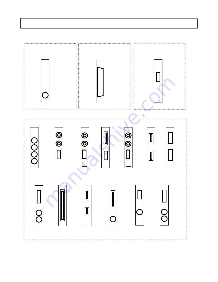
5.5 Connector Configurations for Each Slot
The following connector brackets can be seen on the rear panel.
◆I/O Bracket(Fixed)
RS232C(CH1)
RS232C-CH1
PLUM-001
VIDEO_OUT
◆Video Boards
◆I/O Boards (Selectable)
FIO01
DIDO
◆Frame Grabbers(Selectable)
CAMERA/
EXT_IF
VIDEO_IN
FHC330A
NC
FHC3310(A)
CAMERA_IF
FHC3321(A)
CAMERA_IF
External
Trigger IN
FHC3328
CN3
CN4
VIDEO_IN
FHC3322AFA
External
Trigger IN
VIDEO IN
FHC3310CL
CN2
CN1
RICE-001(a)
CH0
CH1
CH2
CH3
FVC01
CH0
CH1
CONT
FVC02
CH0
CH1
CONT
FVC
02
FVC04
CN1
CONT
FVC05
CH0
CH1
CONT
FVC
05
CN2
CN1
FVC06
CN4
CN3
* This section shows only the shape of each board.
Refer to the manual for each board about connector signal specifications.
- -
41
Summary of Contents for FV3000-W2K
Page 8: ......
Page 13: ...FV3000 3 Mounting Fittings 2 plates with six 3 mm screws ...
Page 18: ...FV3000 8 ...
Page 24: ...FV3000 14 ...
Page 32: ...FV3000 22 ...
Page 46: ...FV3000 36 ...
Page 54: ...FV3000 44 ...
Page 64: ......
Page 66: ...B 001680 1437 ...


