High ef
fi
ciency heat recovery unit with cooling circuit -
RHE
-
13
Selection, installation, use and maintenance manual
GB
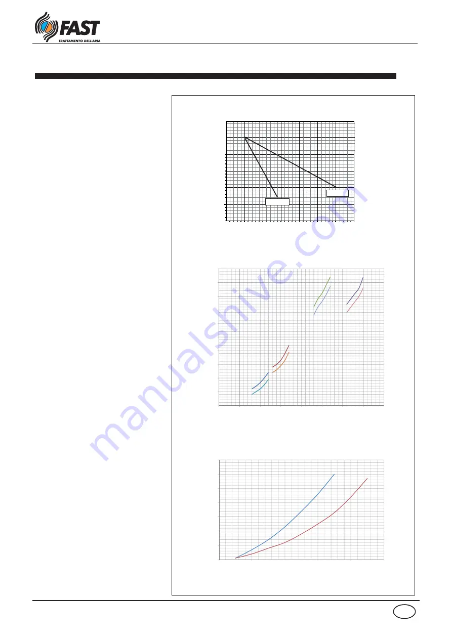
Heating efficiencies and accessories pressure drops BCH, MSS
The diagram in fig. 06 allows to determine
for each model, according to the water
temperature and otside air temperature
variation the corrective factor to multiply for
the nominal capacity value are present in
the technical data table.
Fig. 07 illustrates the pressure drops
(Pa)
on
the air side based on the flow rate for the
MBCH
and
MSS
accessories
Fig. 08 illustrates the pressure drops
(kPa)
water side of the
MBCH
accessory coil.
Note:
The pressure drops illustrated in the
diagram also include those of the three-way
valve.
fig.06
Outside air temperature [°C]
fig.08
Water flow [l/h]
kPa
Air flow [m
3
/h]
Pa
fig.07
70/60°C
Corrective coefficient
Pressure drop on air side
Pressure drop on water side
45/40°C
20
25
30
35
40
45
50
MBCH 25
MSS 1
MBCH 33
MSS 2
0
5
10
15
20
0
500
1000
1500
2000
2500
3000
3500
4000
MBCH 10
MSS 1
MBCH 15
MSS 1
70
50
60
40
50
30
40
20
MBCH
1
10
MBCH
2
0
0
500
1000
1500
2000
2500


