High ef
fi
ciency heat recovery unit with cooling circuit -
RHE
-
25
Selection, installation, use and maintenance manual
GB
Ducts connection
CAUTION!
Never start up the unit when the fan
opening vents are not ducted or covered by
protective mesh.
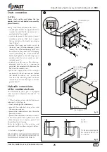
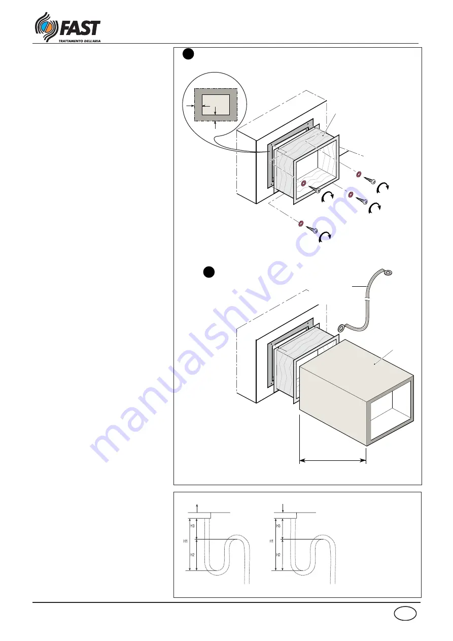
See fig. 10 for the installation of the ducts:
• use adequate brackets to support the ducts
in order to avoid that the recovery unit is
overloaded by their weight;
• in order to prevent the transmission of
vibrations and noise, FAST S.p.A. suggests
the use of ducts with a frontal mass higher
than 10 kg/m
2.;
;
• connect the supply and exhaust vents to
the ducts using vibration-damping joints
(canvas). The vibration-damping joint must
be screwed to the panel with self-tapping
screws, positioning the screws inside the
border highlighted in the following layout
avoiding that the canvas joints are over
stretched (point 1);
• connect a earth wire to the vibration-
damping joint to act as a jumper to
guarantee the unipotentiality between the
ducts and the recovery unit;
• place the supply duct with a straight
section of at least one meter, before
the bends, branches, etc., and make
sure that the ductling does not have
inclinations of the divergent sections
greater than 7°.
Hydraulic connections
of the condensate drain
The condensate drain pan is equipped
with 2 exhaust diameter threaded 1 "G
UNI 338:
- 1)The drainage system should feature an
adequately sized trap to:
• freely discharge the condensate;
• prevent the undesired entry of air into
the vacuum systems;
• prevent the undesired exit of air from the
pressure systems;
• prevent the infiltration of odours or insects.
In the lower part of the syphon must have
a bleed cap or must anyway permit fast
dismantling for its cleaning.
Rules to follow for the scaling and
production of the syphon are given below.
-2) A drain is plugged.
MMMAX
fig.10
Anti-vibration joint
canvas
Electric earthing
cable not sup-
plied
Supply duct
MIn. lenght 1 m
max. divergence 7°
fig.11
H1 = 2P
H2= H1 / 2
P is the pressure expressed in
mm of water column (1 mm
c.a. = 9.81 Pa).
NB. DURING INSTALLATION INCLINE
THE UNIT TO FACILITATE DRAINAGE OF
CONDENSATE FROM THE SIPHON.
P
neg.
P
pos.


